Appearance
Turbulence (T0, T1, T2, T3)
#119 measures what the scheme does to turbulence before anything is built on it. The diagnostics, the keys and the models are in input and numerics.
Contract legs
src/tests/flume/verification/turbulence/check.sh, CPU and FNL.
| Leg | What it verifies | Measured |
|---|---|---|
| tt1 | first history row of taylor-green against the exact integrals, M 0.1, 1.25 | K |
| tt2 | one rank against 2 | |
| tt3 | energy budget to | 70 %, 8.8 %, 0.28 % at |
| tt6 | pressure work, M 0.8: the budget closes only with | 8.5 % left, 203 % without, 414 % flipped |
| ht1 | isotropic-turbulence field: every shell, | shells |
| ht2 | one rank against 2 on the random field | |
| sg1 | the formulas against numpy on 200 tensors; the zeros of each model | |
| sg2 | budget with the model, M 0.4: Vreman 36 %, 5.7 %, 0.27 % left at | at |
| sg3 | no viscosity with each model | |
| sg4 | one rank against 2 with a model | |
| hy1 | inviscid Taylor-Green: dissipated | 47 times less on FNL |
| wm1 | laminar channel, isothermal walls, Re 100: force against | order 1.99, |
| wm2 | test_wall_model; laminar channel on modelled walls | see numerics; order 1.84, 1.9 % at 64 |
| wm3 | half the wall refined, 2:1: force between the coarse and the fine uniform runs | 0.03 % from their mean, mass |
| wm4 | hot wall, modelled against resolved: energy change; one rank against 2 on modelled walls | 7.8 % (bound 10 %); |
| wm5 | matching height 0.3, laminar channel at Re 5 against the exact slip solution | |
| wm6 | semi-local against classical damping on a hot wall, Re 100 | force 0.7 % apart (min 0.01 %) |
| wm7 | input filter: | 0 (bit for bit); |
| wm8 | inverse-transformation model: laminar channel against the equilibrium model; hot wall; one rank against 2 with the filter | |
| wm9 | restart with the filter averages (.wmf, one per rank): 10 steps + restart to 20 against 20 straight, inverse-transformation model, .wmf removed | fields and histories bit for bit (CPU and FNL); the control differs and warns |
| wm10 | dimensional units on a Vreman channel with the wall model and the forcing, gas cp, cv: input bit for bit (NV-5), output against scaling.py dimensionalize (NV-9), forcing and turbulence histories included | bit for bit (CPU and FNL); bit for bit, 4 histories |
| tb2 | wall-model history: | |
| tb1 | digital-filter inflow: the generator's stresses, temporal and spanwise correlations, periodic span, plane restart (test_inflow_df); a Mach 2.5 box: the inflow ghosts carry the table; one rank against 2; restart with the .dff against straight, control without it | stresses 0.4–0.7 % (bound 3 %), correlation exact, integral length 5 % short (bound 10 %); |
| hy3 | the central flux: order, kinetic energy identity, pressure equilibrium | order 5.96–5.99; |
| hy4 | contact of density ratio 8 and 100 | |
| hy5 | 2:1 box, conservation; passes with any skin | mass |
| hy6 | Sod against WENO | L1 |
| hy7 | runtime regridding; a forest with open ends | |
| hy8 | density wave, amplitude 0.2; WENO holds it too, so this does not separate them | |
| hy9 | model only off flagged cells; one rank against 2; conservation (does not prove the mask on ghost cells) | |
| hy11 | relaxing the skin changes the density: seams, open ends (does not catch a shifted band) | |
| hy12 | restart on a refined grid, every cell | 0 |
| hy13 | against WENO, L1: a vortex through a shock (2-D), Shu-Osher and a shock through 2:1 seams (1-D, no vorticity, so the Ducros ratio flags any varying flow): robustness, no accuracy claim |
Taylor-Green vortex: the ILES baseline
Re 1600, runge-kutta-ssp-54, CFL 0.5, weights = si, 4 ranks on A30, from turbulence/tgv_campaign.sh. weno is the flux splitting, HLLCweno-riemann with the 6th-order correction and the WENO sensor. All values per unit volume.
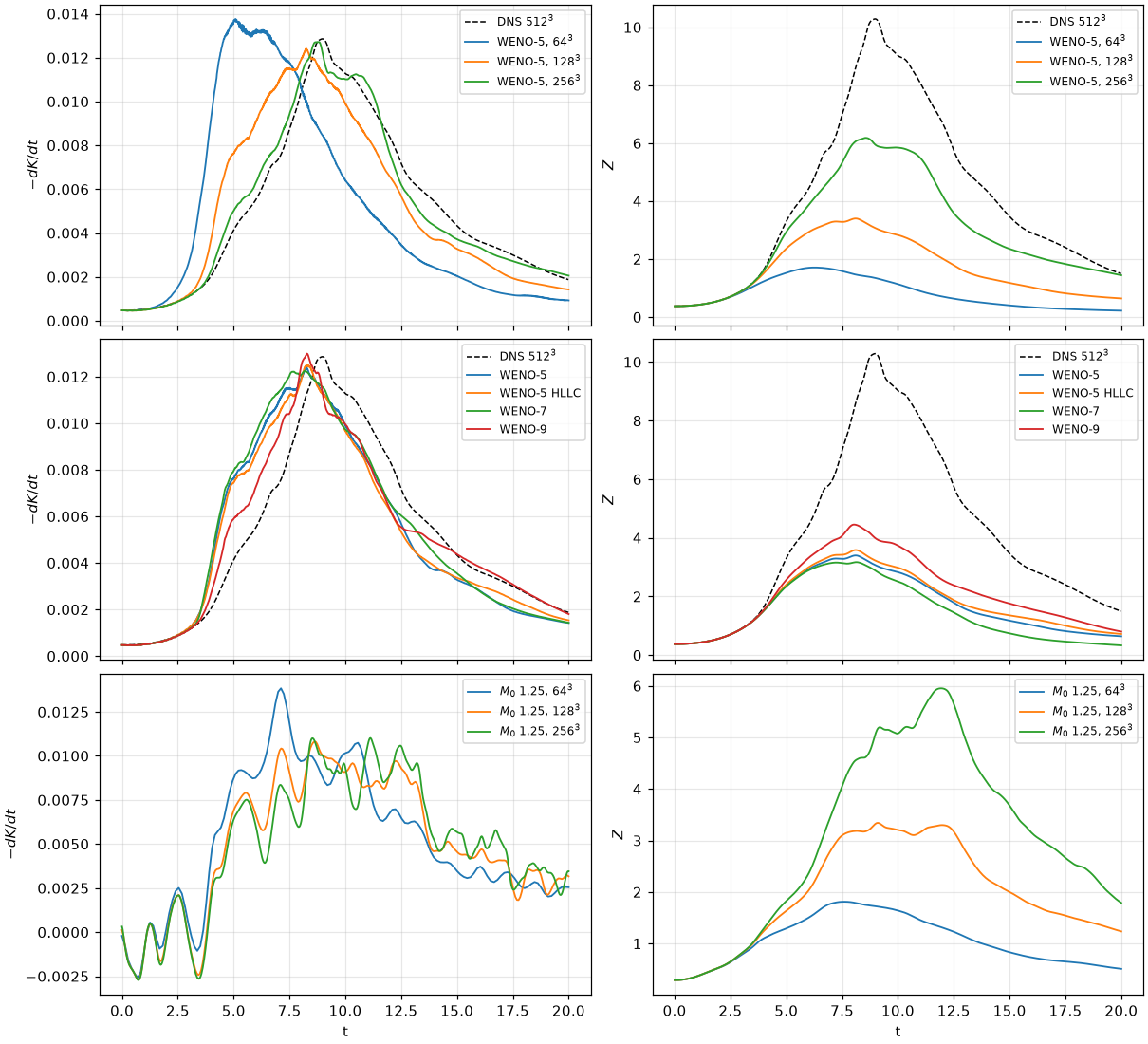
Top: M 0.1, WENO-5 by resolution; middle: M 0.1 at
| Case | Peak | at | Peak | at | Numerical share to the peak | |
|---|---|---|---|---|---|---|
| M 0.1, WENO-5, | 0.01377 | 5.08 | 1.71 | 6.25 | 77 % | 0.0245 |
| M 0.1, WENO-5, | 0.01242 | 8.24 | 3.40 | 8.11 | 58 % | 0.0219 |
| M 0.1, HLLC, | 0.01305 | 5.42 | 1.83 | 6.56 | 76 % | 0.0284 |
| M 0.1, HLLC, | 0.01249 | 8.28 | 3.59 | 8.11 | 55 % | 0.0227 |
| M 0.1, WENO-7, | 0.01224 | 8.19 | 3.17 | 8.14 | 60 % | 0.0181 |
| M 0.1, WENO-5, | 0.01272 | 8.75 | 6.18 | 8.56 | 27 % | 0.0223 |
| M 0.1, WENO-9, | 0.01299 | 8.28 | 4.45 | 8.03 | 43 % | 0.0213 |
| 0.01383 | 7.12 | 1.81 | 7.62 | 80 % | 0.0206 | |
| 0.01081 | 8.62 | 3.34 | 9.09 | 46 % | 0.0243 | |
| 0.01101 | 11.12 | 5.95 | 11.94 | 20 % | 0.0245 | |
| 0.01246 | 7.22 | 2.29 | 7.72 | 69 % | 0.0299 | |
| 0.01120 | 8.56 | 3.86 | 11.44 | 36 % | 0.0265 | |
| 0.01122 | 11.11 | 6.31 | 11.99 | 14 % | 0.0243 |
The share is that of the energy lost until the peak of
Reference. The 512³ pseudo-spectral DNS of the High-Order CFD Workshop (case C3.5, turbulence/reference/spectral_Re1600_512.gdiag), incompressible, so compared at M 0.1 only: peak
What it shows.
- Numerical dissipation dominates: up to the peak of
it is 77 % of the energy lost at and 58 % at with WENO-5 at M 0.1. At the enstrophy peak is a third of the reference, so the resolved gradients are far from converged even where the total looks right. At the peak of comes at . - Scheme and order matter less than resolution at
: HLLC gains a few percent, WENO-9 reaches 4.45. WENO-7 is below WENO-5 ( 3.17 against 3.40), which is not explained. - At
the numerical share falls with the resolution, 80 %, 46 %, 20 %.
Subgrid-scale models (T1) and the go/no-go
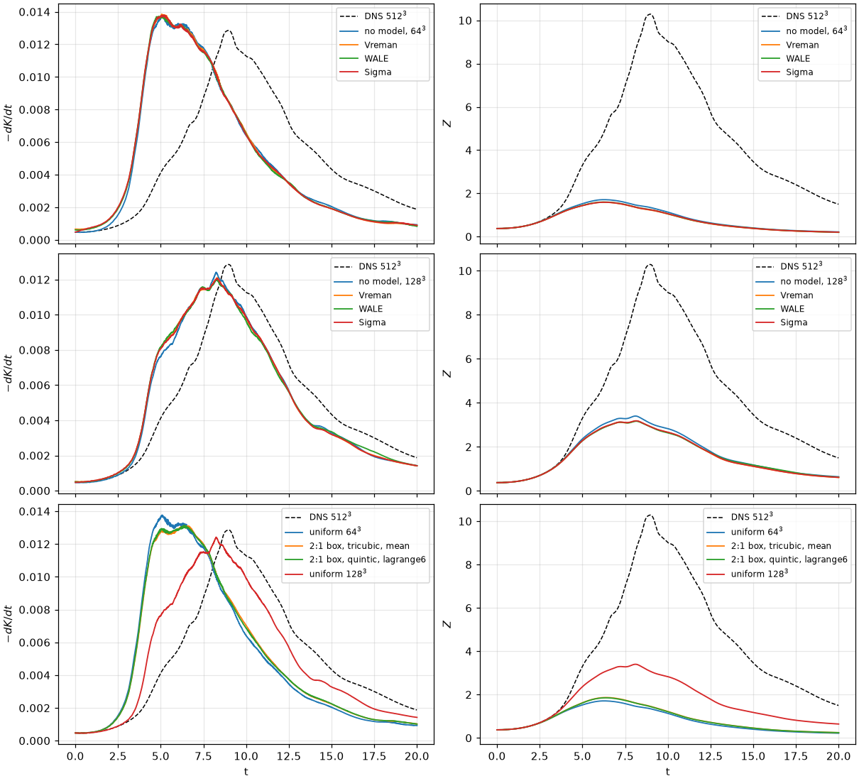
Top: M 0.1 at
| Case, M 0.1 | Peak | at | Peak | Numerical share to the peak | |
|---|---|---|---|---|---|
| no model, | 0.01377 | 5.08 | 1.71 | 77 % | 0.0245 |
| Vreman, | 0.01385 | 5.05 | 1.59 | 79 % | 0.0236 |
| WALE, | 0.01374 | 5.04 | 1.60 | 79 % | 0.0239 |
| Sigma, | 0.01380 | 5.17 | 1.59 | 79 % | 0.0237 |
| no model, | 0.01242 | 8.24 | 3.40 | 58 % | 0.0219 |
| Vreman, | 0.01210 | 8.29 | 3.18 | 61 % | 0.0213 |
| WALE, | 0.01199 | 8.29 | 3.16 | 61 % | 0.0210 |
| Sigma, | 0.01206 | 8.30 | 3.18 | 60 % | 0.0213 |
Here the share leaves out the model's own dissipation, so it is not a pure numerical share:
No model beats no model on this measure. On a dissipative scheme each one lowers the enstrophy peak further from the reference (1.59 against 1.71 at
The effect of a 2:1 box (T0.6)
M 0.1, base amr_iterations = 0), found because the runs equal the uniform grid to every digit.
| Case | Peak | at | Peak | at | ||
|---|---|---|---|---|---|---|
| uniform | 0.01377 | 5.08 | 1.71 | 6.25 | 0.0245 | 0.00026 |
| box, tricubic fill, mean restriction | 0.01312 | 6.39 | 1.87 | 6.39 | 0.0233 | 0.0070 |
box, quintic fill, lagrange6 | 0.01314 | 6.39 | 1.85 | 6.38 | 0.0234 | 0.0115 |
| uniform | 0.01242 | 8.24 | 3.40 | 8.11 | 0.0219 | 0.00007 |
The box delays the peak of
Decaying compressible isotropic turbulence (T0.5)
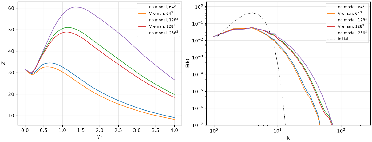
Left: the enstrophy against
| Case | Peak | at | |||
|---|---|---|---|---|---|
| no model, | 34.5 | 0.66 | 0.303 | ||
| Vreman, | 32.6 | 0.58 | 0.292 | ||
| no model, | 51.0 | 1.14 | 0.384 | ||
| Vreman, | 48.9 | 1.12 | 0.376 | ||
| no model, | 60.5 | 1.36 | 0.413 |
The hybrid central/WENO scheme (T2)
scheme_space = hybrid-kep-weno (numerics), the same inputs.
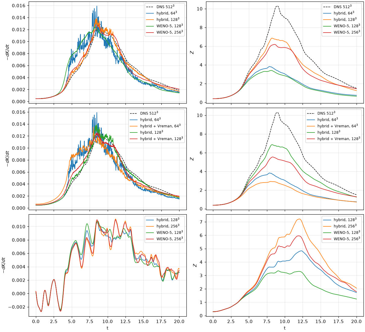
Top: M 0.1, the hybrid against WENO-5; middle: with Vreman; bottom:
| Case, M 0.1 | Peak | Over | at | Flicker, | Peak | Numerical share to the peak |
|---|---|---|---|---|---|---|
| WENO-5, | 0.01377 | 0.01357 | 5.09 | 0.3 % | 1.71 | 77 % |
| hybrid, | 0.01591 | 0.01334 | 8.09 | 7.2 % | 3.82 | 50 % |
| hybrid + Vreman, | 0.01347 | 0.01173 | 8.21 | 3.5 % | 2.92 | |
| WENO-5, | 0.01242 | 0.01216 | 8.29 | 0.5 % | 3.40 | 58 % |
| hybrid, | 0.01389 | 0.01317 | 8.48 | 2.0 % | 6.86 | 18 % |
| hybrid + Vreman, | 0.01258 | 0.01226 | 8.58 | 0.8 % | 5.53 | |
| WENO-5, | 0.01272 | 0.01261 | 8.72 | 0.7 % | 6.18 | 27 % |
The flicker is the rms of
| Case, | Peak | Peak | Numerical share |
|---|---|---|---|
| WENO-5, | 0.01383 / 0.01081 / 0.01101 | 1.81 / 3.34 / 5.95 | 80 % / 46 % / 20 % |
| hybrid, | 0.01266 / 0.01057 / 0.01112 | 2.20 / 4.83 / 7.21 | 73 % / 36 % / 10 % |
Isotropic turbulence: peak
What it shows.
- At M 0.1 the hybrid reaches at
a higher enstrophy peak than WENO-5 at , and at more than WENO-5 at , with the dissipation peak where the finer runs have it. is still below the quoted 10.3. - At
the gain is smaller, as the sensor keeps WENO around the shocklets. - The raw peak of
is not a measure on the hybrid: it flickers, 7 % at , 2 % at . The source is not established; the sensor switching on and off is the first candidate. Smoothed, the hybrid is 4–6 % above WENO-5 at . - Vreman on the hybrid removes half of the flicker and lowers
by 20 %. At it lands below the finer runs (0.0117). Against the DNS it makes the hybrid worse at both resolutions (below). - The thresholds (0.2, 0.1) and the floor are not calibrated.
On a 2:1 box, and what the skin costs
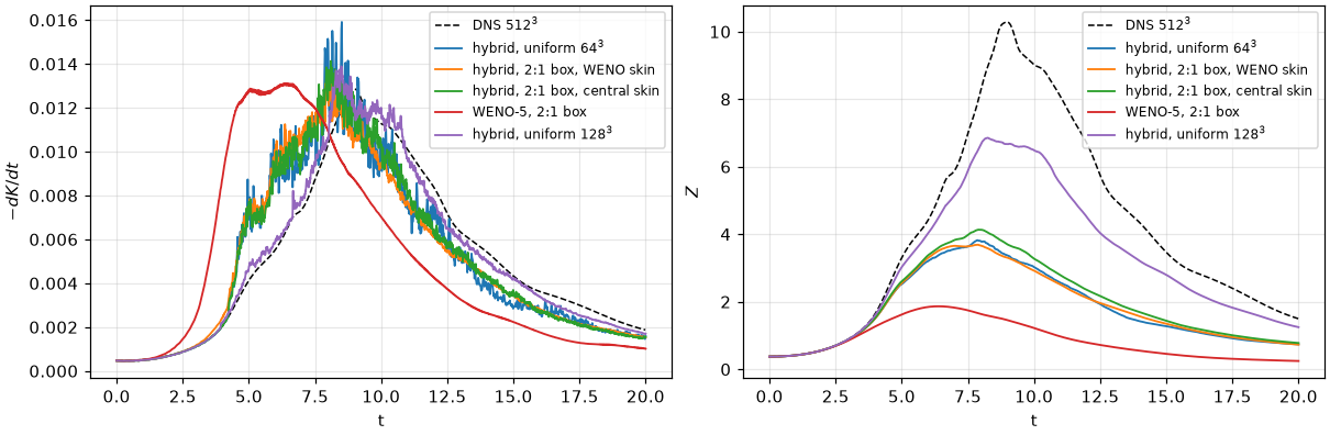
M 0.1, a box of half the side refined once on
| Case | Smoothed peak | Peak |
|---|---|---|
| WENO-5, box | 0.01304 | 1.87 |
| hybrid, box, WENO skin (default) | 0.01239 | 3.69 |
| hybrid, box, central skin | 0.01319 | 4.13 |
| hybrid, uniform | 0.01333 | 3.82 |
With the WENO skin the box ends below the uniform run in
Against the DNS
M 0.1 against the 512³ DNS, from turbulence/tgv_dns.py. Peak
| Case | Peak | at | Peak | at | L2 | L2 | L2 |
|---|---|---|---|---|---|---|---|
| DNS | 0.01286 | 8.97 | 10.29 | 8.97 | |||
| WENO-5, | 0.01357 | 5.09 | 1.709 | 6.25 | 0.660 | 0.844 | 0.187 |
| WENO-5, | 0.01216 | 8.29 | 3.400 | 8.11 | 0.278 | 0.643 | 0.083 |
| WENO-5, | 0.01260 | 8.72 | 6.182 | 8.56 | 0.090 | 0.331 | 0.020 |
| HLLC, | 0.01235 | 8.32 | 3.585 | 8.11 | 0.260 | 0.623 | 0.070 |
| WENO-7, | 0.01215 | 8.11 | 3.171 | 8.14 | 0.291 | 0.688 | 0.101 |
| WENO-9, | 0.01274 | 8.27 | 4.454 | 8.03 | 0.177 | 0.539 | 0.037 |
| Vreman, | 0.01373 | 5.11 | 1.591 | 6.23 | 0.671 | 0.854 | 0.200 |
| Vreman, | 0.01193 | 8.28 | 3.177 | 8.15 | 0.295 | 0.662 | 0.092 |
| WALE, | 0.01183 | 8.26 | 3.164 | 8.16 | 0.296 | 0.660 | 0.091 |
| Sigma, | 0.01192 | 8.29 | 3.184 | 8.14 | 0.293 | 0.660 | 0.091 |
| WENO-5, 2:1 box | 0.01304 | 6.41 | 1.865 | 6.39 | 0.617 | 0.829 | 0.178 |
| hybrid, | 0.01333 | 8.09 | 3.822 | 7.86 | 0.237 | 0.615 | 0.057 |
| hybrid, | 0.01317 | 8.47 | 6.856 | 8.25 | 0.067 | 0.271 | 0.014 |
| hybrid + Vreman, | 0.01173 | 8.21 | 2.917 | 8.09 | 0.283 | 0.678 | 0.086 |
| hybrid + Vreman, | 0.01226 | 8.58 | 5.529 | 8.33 | 0.114 | 0.400 | 0.029 |
| hybrid, 2:1 box, WENO skin | 0.01239 | 8.14 | 3.688 | 7.88 | 0.269 | 0.618 | 0.063 |
| hybrid, 2:1 box, central skin | 0.01319 | 8.11 | 4.134 | 7.91 | 0.236 | 0.580 | 0.059 |
- The hybrid at
is closer than WENO-5 at on all three errors, with one eighth of the cells. At it is closer than WENO-5 at . - Its peak of
is 2.4 % above the DNS and comes at rather than 8.97; at reaches two thirds of the DNS peak, so the gradients are not converged. - A model makes it worse: Vreman takes the
error from 0.067 to 0.114 and the error from 0.27 to 0.40 at . All three models also worsen WENO-5. This flow at Re 1600 is not a case where the subgrid scales are far from resolved, and the constants were not tuned; on these integrals no model is recommended here. - WENO-9 at
(0.177) is much closer than WENO-5 (0.278); WENO-7 is further (0.291), still unexplained. - The skin: on the 2:1 box the WENO skin (0.269) is further than uniform
(0.237); the central skin ties it on (0.236) and beats it on (0.580 against 0.615). Smooth flow only.
Cost
200 steps on
Plane channel and the wall model (T3)
Coleman, Kim & Moser (1995): bulk Mach 1.5, bulk Re 3000 on the half height and the wall viscosity, isothermal walls, viscosity turbulence/channel_campaign.sh with channel_cases_t35.txt, 4 A30, after the no-slip leak fix.
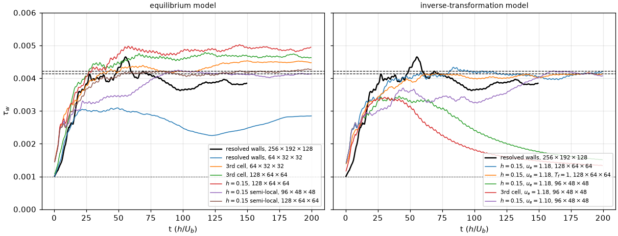
| Case | Cells | ||||
|---|---|---|---|---|---|
| resolved walls | 3.82e-3 | – | 211 ( | 1.16, 1.26 | |
| resolved walls | 2.35e-3 | 2.72e-3 | 166, 178 | 1.22, 1.26 | |
| equilibrium, 3rd cell | 4.37e-3 | 4.49e-3 | 226, 229 | 1.21, 1.29 | |
| equilibrium, 3rd cell | 4.36e-3 | 4.52e-3 | 226, 230 | 1.19, 1.30 | |
| equilibrium, 3rd cell | 4.69e-3 | 4.66e-3 | 234, 234 | 1.18, 1.31 | |
| equilibrium, 3rd cell, semi-local | 4.33e-3 | 4.33e-3 | 225, 225 | 1.18, 1.30 | |
| equilibrium, | 4.71e-3 | 4.77e-3 | 235, 236 | 1.19, 1.30 | |
| equilibrium, | 4.89e-3 | 4.90e-3 | 239, 239 | 1.19, 1.30 | |
| equilibrium, | 4.15e-3 | 4.09e-3 | 220, 219 | 1.18, 1.29 | |
| equilibrium, | 4.13e-3 | 4.21e-3 | 220, 222 | 1.17, 1.29 | |
| … and the filter | 4.15e-3 | 4.03e-3 | 220, 217 | 1.18, 1.29 | |
| … and the filter | 4.15e-3 | 4.16e-3 | 220, 221 | 1.19, 1.29 | |
| inverse, | 4.13e-3 | 4.08e-3 | 220, 218 | 1.16, 1.21 | |
| … and the filter | 4.04e-3 | 4.11e-3 | 217, 219 | 1.17, 1.21 | |
| inverse, | 2.03e-3 | 1.62e-3 | 154, 138: relaminarises | 1.51, 1.11 | |
| inverse, 3rd cell, | 1.61e-3 | 1.40e-3 | 137, 128: relaminarises | 1.44, 1.12 | |
| inverse, | 3.61e-3 | 4.15e-3 | 206, 220 | 1.18, 1.21 |
The inverse model's edge state is given (
What it shows.
- Matching height 0.15 with semi-local damping puts the equilibrium model in the DNS band on both grids (219–222). Either change alone is worse: the 3rd-cell sample is 226–234 and rises with the grid,
with the classical damping 235–239, the semi-local damping at the 3rd cell 225. The fixed height removes the grid trend; the semi-local damping removes the excess. This is one Mach and Reynolds number, single runs, and the band sits within the of the wall density. - The input filter does not move the means (within 1.5 %); on the coarser grid it slows the transient.
- The inverse model is in the band on the finer grid with a cooler centreline (
1.21 against 1.29 for the equilibrium model, 1.26 for the resolved run): its heat flux differs. On it relaminarises with , at and at the 3rd cell, but not with : the model is sensitive to the given edge velocity, which the flow does not set (the paper takes the edge from the flow; a face kernel cannot). Why 1.18 drains the turbulence on that grid is not explained. - The wall-resolved reference did not change with the leak fix (211 against 211 before,
), so its 4–5 % shortfall from the DNS was not the leak: its resolution or the hybrid scheme's dissipation, not tested. The modelled rows in the band agree with the DNS, not with it. - The coarse grid with resolved walls still falls 20 % short: without a model the grid cannot carry the wall layer.
- Only
and the centreline are compared: no averaged profiles, and the DNS profiles are not in this tree.
Mach 3
Result first: with the wall model's eddy viscosity below wall_model_eddy_viscosity, below) and run to a thermal steady state at
Without a flux path below
Coleman, Kim & Moser's second case: bulk Mach 3, bulk Re 4880, channel_cases_t3_mach3.txt. The wall density changes with the run at this Mach number, so each row takes its own: channel_wall_cells.py budget;
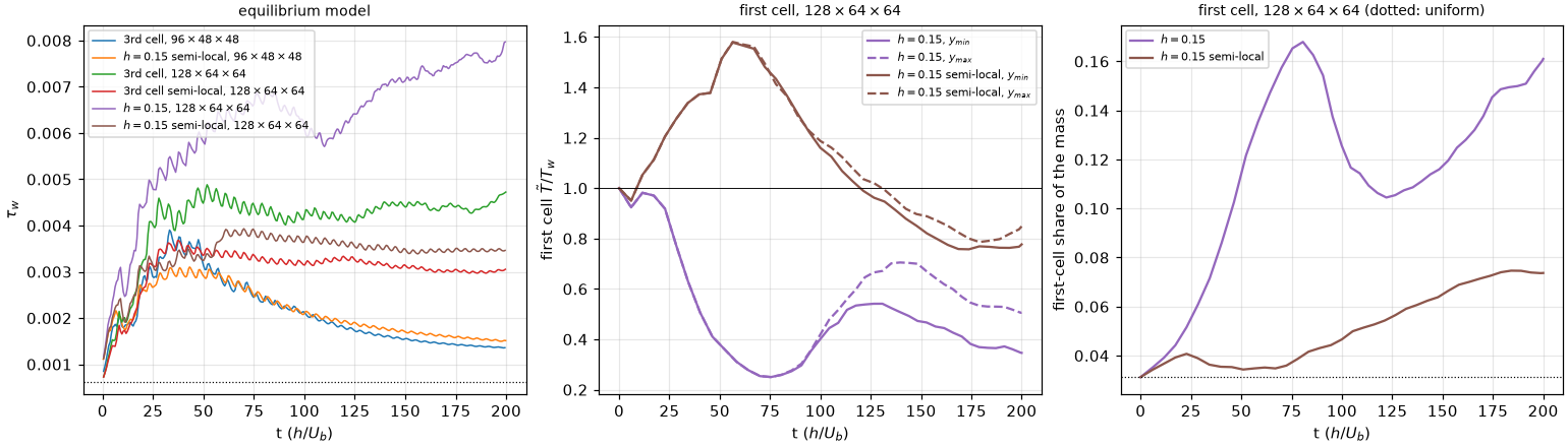
Left: channel_cases_t3_mach3_drain.txt, the same runs, bitwise).
| Case | Cells | |||||||
|---|---|---|---|---|---|---|---|---|
| equilibrium, 3rd cell | 1.77e-3 | 1.43e-3 | 1.65 | 264, 238: relaminarises | 1.43, 1.63 | 0.86 | 0.71 | |
| equilibrium, | 1.89e-3 | 1.59e-3 | 1.54 | 263, 241: relaminarises | 1.50, 1.53 | 0.64 | 0.67 | |
| equilibrium, 3rd cell | 4.29e-3 | 4.44e-3 | 2.12 | 465, 473 | 1.25, 2.22 | 1.03 | 0.87 | |
| equilibrium, 3rd cell, semi-local | 3.20e-3 | 3.03e-3 | 2.02 | 392, 381 | 1.20, 2.04 | 1.28 | 0.85 | |
| equilibrium, | 3.58e-3 | 3.46e-3 | 1.91 | 404, 397 | 1.28, 2.01 | 0.81 | 0.83 | |
| equilibrium, | 6.46e-3 | 7.49e-3 | 2.12 | 571, 615: still rising | 1.48, 2.63 | 0.41 | 0.88 |
What it shows.
- No run is at a thermal steady state at
: the total energy still rises in every run ( 0.67–0.88), so these are values on the way, not means. - The Mach 1.5 setting does not carry over:
with semi-local damping is 12 % below the DNS; the 3rd-cell sample is 5 % above. The coarse grid relaminarises with either setting. - The first cell is drained. The wall face takes the modelled
and from the sample at ; the first cell's own state never enters, and nothing below carries those fluxes (no subgrid model): the molecular plus resolved stress at the face between cells 1 and 2 is 0.54 with semi-local damping and 0.21–0.39 with the classical one (after ). With and the classical damping the first cell falls to , reverses its flow and holds 17 % of the mass at ; follows it, also down ( 80–110) and up again: the run does not settle. With semi-local damping the drain is slower and stays flat, but the first cell is still below from . A first cell colder than an isothermal wall that takes heat out of it is not a boundary layer: the treatment below , not the model's law, is what fails here.
With the eddy viscosity below
The face key wall_model_eddy_viscosity = .true. sets channel_cases_t3_mach3_ev.txt), then continued from the restart to channel_cases_t3_mach3_ev800.txt).
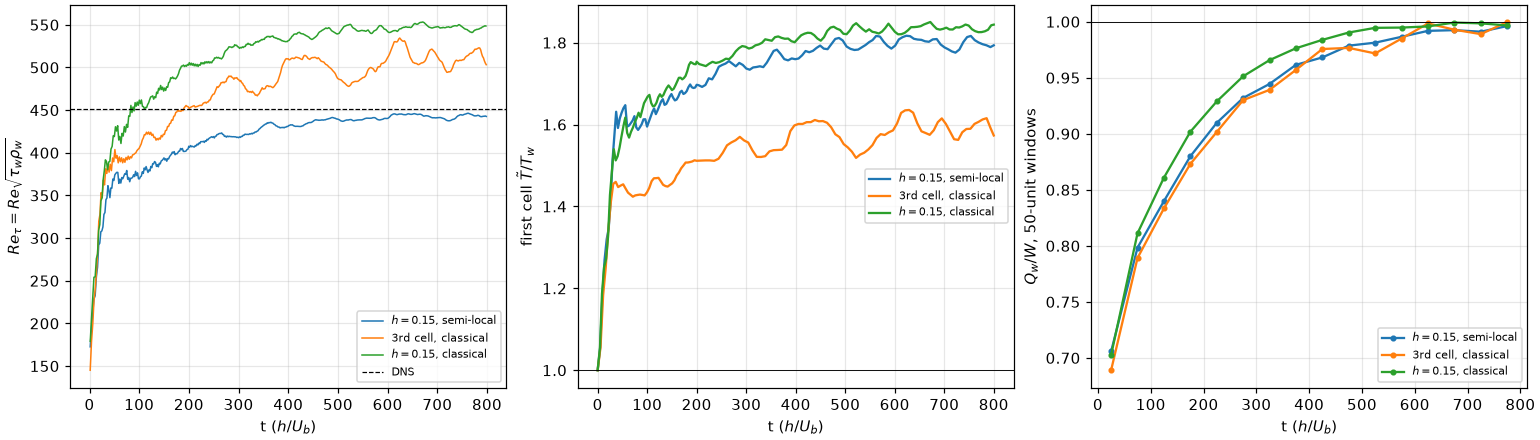
Left:
| Case | |||||||
|---|---|---|---|---|---|---|---|
| equilibrium, | 3.52e-3 | 3.48e-3 | 2.36 | 445, 443 | 1.17, 2.44 | 1.79 | 0.99 |
| equilibrium, 3rd cell | 4.51e-3 | 4.35e-3 | 2.51 | 519, 510 | 1.21, 2.65 | 1.57 | 0.99 |
| equilibrium, | 5.17e-3 | 5.15e-3 | 2.44 | 548, 547 | 1.21, 2.53 | 1.84 | 1.00 |
What it shows.
- The drain is gone. The first cell is
– at every time after the transient, the two walls agree within 2 %, and the two first-cell layers hold 4–5 % of the mass (3.1 % if uniform), against 16 % at without the key. - The runs are thermally steady at
: is 0.99–1.00 and about 60 times smaller than at . with semi-local damping matches the DNS within 2 %. With the classical damping is 13 % (3rd cell) and 21 % ( ) above. needs the thermal steady state at this Mach number. The bulk heats until , rises from about 2.1 to 2.4–2.5, and rises with it: at the 3rd-cell run gave 438, 448, which looked like a match. - Cost: from the same
state of the semi-local run to (medooza, 4 A30), the key on takes 1.69 times the wall time of the key off: 1.28 times the steps (the eddy viscosity enters the viscous time-step limit) and 1.32 times the time per step.
Compressible boundary layer (T3.7)
The zero-pressure-gradient layer of the DNS of Zhang, Duan & Choudhari (2018, AIAA J 56(11)), case M2p5: Mach 2.5, adiabatic wall (turbulence/reference/). The layer is fed through the face inflow-digital-filter (numerics): the DNS station profile scaled to the inflow thickness [diagnostics] wall_history_save (leg tb2).
| Setup | |
|---|---|
| box, cells | |
| gas | |
| wall | wall-modelled, |
| inflow | integral lengths |
| scheme | hybrid-kep-weno, no subgrid model |
| run | tbl_cases_t37_l90.txt, to tbl_oracle.py compare); 0.40 s per step on 4 A30 |
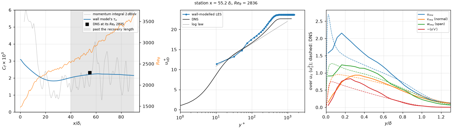
Left:
| At | LES | DNS |
|---|---|---|
| 2.21e-3 (the two halves of the window 2.19e-3, 2.22e-3) | 2.31e-3 | |
| 1.56e-3 | ||
| 4.08 | 4.10 (its profile: 4.22) | |
| 13.1, 17.5, 19.8 | 13.6, 16.7, 18.8 | |
| 2.06, 0.81, 1.22 | 1.49, 0.93, 1.12 | |
| 0.80, 0.50 | 0.62, 0.37 |
What it shows.
within 4.4 % of the DNS at its , with the setting that matched the Mach 3 channel. The two halves of the averaging window differ by 1.1 %. Most of the 4.4 % is the inflow's recovery, not the plateau: farther downstream, at – , is within 1.6–0.4 % of the DNS's value scaled as , and at it is 0.3 % at the station (resolution). - The inflow recovers by
. The layer reaches the DNS's at , against 53 in the DNS. falls from at the inlet to at , the adaptation of the synthetic eddies, then rises to a plateau of from . That matches the recovery length of a digital filter at this Mach number (Huang, Duan & Choudhari 2022). - The momentum integral does not measure
here. Fitted over , swings between and along on the same averaged data, and is % at the station. A first run on a box had only this estimate, and it reported 16–28 % low. - The log layer sits 0.9–1.0 above the DNS in
, and peaks too high, the near-wall streaks of a coarse LES. The resolved in the outer layer is above the DNS's. At the log layer, and move toward the DNS. , taken against the local free stream as the DNS takes it, is the DNS's within 1 % (4.08).
Resolution: Mach 2.5 at
The Mach 2.5 case on the same tbl_cases_t37_r16.txt, 35264 steps, 0.80 s per step on 4 A30).
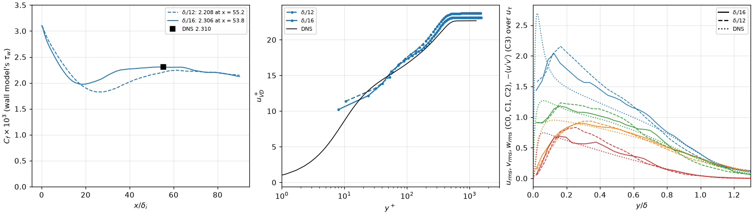
Left:
| DNS | |||
|---|---|---|---|
| 2.208e-3 (halves 2.195e-3, 2.220e-3) | 2.306e-3 (halves 2.299e-3, 2.312e-3) | 2.310e-3 | |
| −12.0, −3.9, −1.6, −0.9, −0.4 % | −3.6, −0.3, +1.0, +0.7, −0.5 % | ||
| 4.08 | 4.23 | 4.10 (its profile: 4.22) | |
| 13.1, 17.5, 19.8 | 12.8, 17.3, 19.2 | 13.6, 16.7, 18.8 | |
| 2.06, 0.81, 1.22 | 1.79, 0.83, 1.16 | 1.49, 0.93, 1.12 | |
| 0.80, 0.50 | 0.66, 0.43 | 0.62, 0.37 |
What it shows.
is grid-converged once the layer has recovered. Downstream of ( ) the two grids agree with each other and with the DNS's scaled as within 1–2 %. The scaling is an approximation (the DNS file holds one station), so these figures carry its error too. - The finer grid shortens the inflow's recovery. The
dip after the inlet ends by at , against – at : the % at the DNS station of the run is mostly the layer still recovering. At the station is past it, and is %; the halves of the window differ by 0.6 %. - The near-wall and log-layer statistics converge toward the DNS: the
peak at from 2.06 to 1.79, from 0.80 to 0.66, the log-layer offset in at from +1.0 to +0.4. is the DNS's on both grids (4.08, 4.23, against 4.10) once taken against the local free stream (the shape factor).
The shape factor and the free stream
The DNS's profiles are normalised by its free stream at the station, and are 1 there. The run's free stream is not the nominal one: the layer thickens downstream and turns the supersonic stream over it, a weak compression of order tbl_oracle.py compare takes
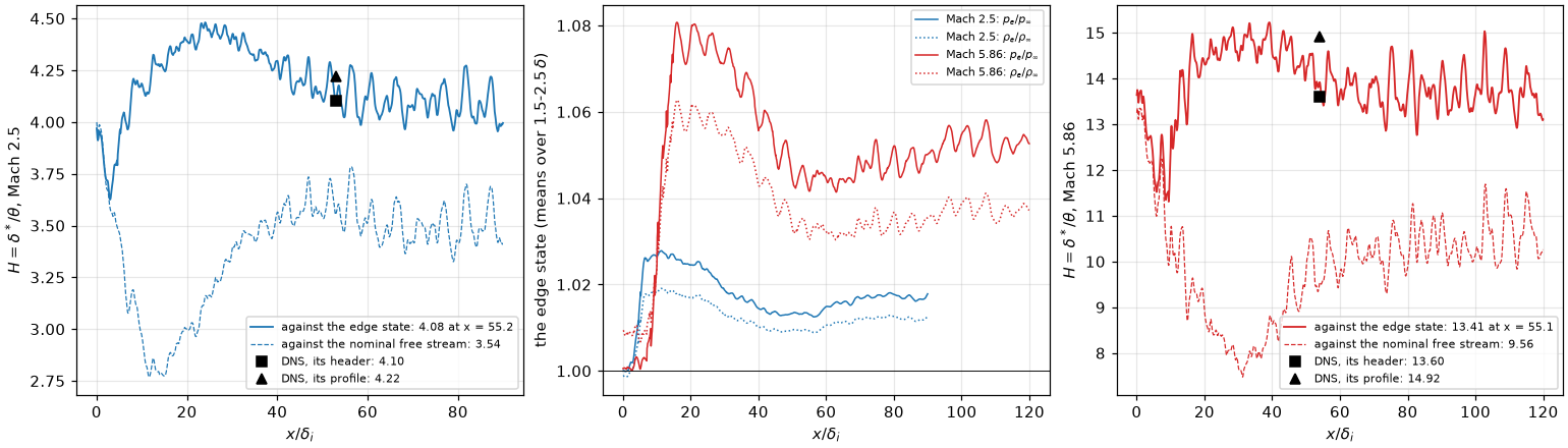
Left and right:
- The free stream is compressed. At Mach 2.5
rises to 1.027 at and is 1.013 at the station, 1.009; at Mach 5.86 1.08 and 1.042. Integrated to the top of the box ( , more than ), the denser stream over the layer takes 0.5 off at Mach 2.5 and 4 at Mach 5.86. The dip of the nominal to 2.8 at is the compression's peak, not the layer. - Against the edge state
is the DNS's: 4.08 at Mach 2.5 (4.10, its profile 4.22), 13.4 at Mach 5.86 (13.6, its profile 14.9). Taken over – , – or – , the edge moves it by 0.04 at Mach 2.5.
Five runs at tbl_cases_t37_hdef.txt), and an algebraic subgrid model, [turbulence] sgs_model = wale and vreman, their default constants (tbl_cases_t37_sgs.txt; WALE on dev-gn, Vreman on prod-gn). Same averaging, 33–35 checkpoints of
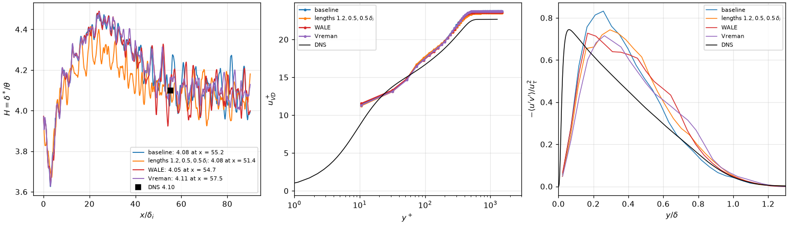
Four of the runs (the span of
| At | baseline | lengths | span | WALE | Vreman | DNS |
|---|---|---|---|---|---|---|
| station | 55.2 | 51.4 | 54.6 | 54.7 | 57.5 | 53 |
| 4.08 | 4.08 | 4.11 | 4.05 | 4.11 | 4.10 (its profile: 4.22) | |
| 2.208e-3 (−4.4 %) | 2.248e-3 (−2.7 %) | 2.205e-3 (−4.6 %) | 2.235e-3 (−3.3 %) | 2.206e-3 (−4.5 %) | 2.310e-3 | |
| 13.1, 17.5, 19.8 | 13.0, 17.7, 19.8 | 13.0, 17.5, 19.9 | 13.2, 17.4, 19.7 | 13.0, 17.5, 19.7 | 13.6, 16.7, 18.8 | |
| 2.06, 0.81, 1.22 | 1.97, 0.75, 1.15 | 2.08, 0.79, 1.22 | 1.97, 0.76, 1.19 | 1.94, 0.74, 1.27 | 1.49, 0.93, 1.12 | |
| 0.80, 0.50 | 0.66, 0.57 | 0.74, 0.56 | 0.72, 0.55 | 0.66, 0.49 | 0.62, 0.37 |
What it shows.
- None of the settings changes the layer much.
stays within 0.06 of the DNS's header value, within 2 % of the baseline's; longer integral lengths shorten the inflow's recovery a little (the layer reaches at , −2.7 %), as did. - The subgrid model is active, and does not matter at this grid. WALE's eddy viscosity, computed from a checkpoint, is about 1.5 times the molecular one over
– and 0.4 at the edge. - What is left is in the stresses, not in the mean: the outer
is 0.49–0.57 at against 0.37 in every run, and the near-wall peak 1.9–2.1 against 1.5. At both move toward the DNS (resolution).
Mach 5.86, cold wall
Case M6Tw076 of the same DNS: Mach 5.86, a cold wall (
| Setup | |
|---|---|
| box, cells | |
| gas | tbl_oracle.py compare --re-inf) |
| wall, inflow, scheme | as at Mach 2.5 |
| run | tbl_cases_t37_m6.txt, to |
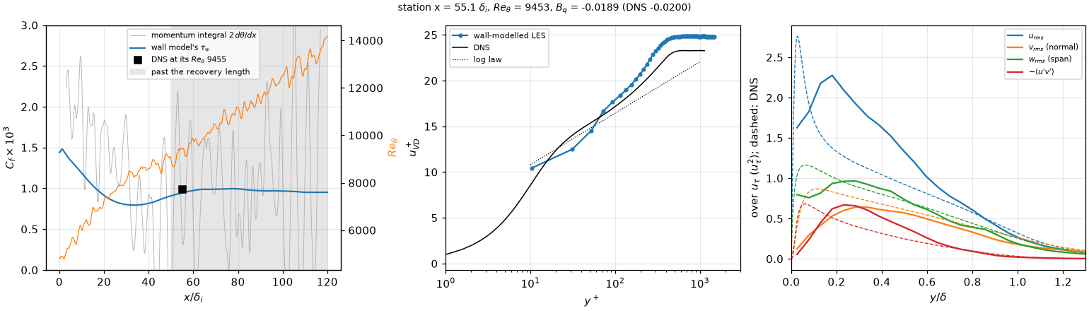
The panels of the Mach 2.5 figure; the title adds
| At | LES | LES, Sutherland | DNS |
|---|---|---|---|
| 9.47e-4 (the two halves of the window 9.70e-4, 9.25e-4); | 9.51e-4; | 9.84e-4 | |
| −0.0189 (halves −0.0191, −0.0187); | −0.0190 | −0.02 (one significant figure) | |
| 1.61 | 1.61 | 1.72 | |
| 13.41 | 13.71 | 13.6 (its profile: 14.9) | |
| 12.4, 17.9, 20.8 | 12.4, 17.9, 20.6 | 13.9, 17.2, 19.5 | |
| 2.21, 0.56, 0.94 | 2.24, 0.55, 0.90 | 1.33, 0.82, 0.99 | |
| 0.64, 0.39 | 0.65, 0.35 | 0.49, 0.25 |
What it shows.
within 3.8 % of the DNS at its , with no change of the wall-model setting from Mach 2.5; past the plateau is 0.7 % below. agrees to the precision of the reference: the DNS file gives , one significant figure, and the run gives 0.0189 at the station, 0.0194 on the plateau. drifts by 4.6 % between the two halves of the window; by 0.4 %. The layer itself changes slowly over the window, and the wall model's heat flux follows its friction. 180 time units are 1.5 flow-throughs of this box, so the figure carries about %. - The inflow recovers by
– , farther than at Mach 2.5 (50): falls from at the inlet to at , then rises to its plateau. The layer reaches the DNS's at , against 54 in the DNS. is the DNS's against the edge state (13.4; the header 13.6, its profile 14.9): the free stream over this layer is compressed by 4 % (the shape factor). - The stresses have the Mach 2.5 faults, larger.
is 6 % thin; peaks at 1.7 times the DNS's at , and is 1.5 below the DNS at (the first cells under the matching point) and 0.7–1.3 above it at – . At the layer of has about 20 cells across ; at Mach 2.5 a finer grid moves the log layer and the stresses toward the DNS (resolution). - Sutherland's law with the DNS's Reynolds number changes little. The viscosity, matched at the wall, is 1.41 times the DNS's in the free stream. A run under Sutherland's law (
viscosity_law = sutherland,K, the DNS's per ; tbl_cases_t37_hdef.txt, 29 checkpoints) removes that:13.71 against 13.41, −3.4 % against −3.8 % at the station, the plateau 9.80e-4, −0.0190. - The momentum integral is useless here too (
% at the station, negative in places).
Not done
- HLLC at
, M 0.1 was dropped by owner decision. - Spectra against the DNS: the file holds integrals only. The DNS of Johnsen et al. for the isotropic case.
- Calibration of the sensor; a model masked by face rather than by cell;
central-bcson a forest seam. - T3: why the classical damping overshoots at Mach 3; a cheaper flux path below
; the boundary layer: the matching height, the outer-layer and near-wall stresses at , a longer window at Mach 5.86; and the station against the edge state (they use the nominal free stream); SBLI; runtime regridding along a modelled wall; mean profiles against the DNS; the relaminarisation of the inverse model on with ; an edge state taken from the flow. - A model on 2:1 grids beyond conservation; runtime AMR with a model; a wall.