
Appearance
Plane channel and the wall model
| ID | Milestone | Type | Legs | Backends | Figure |
|---|---|---|---|---|---|
| WM | #119 · T3.1–T3.6 | P+C | wm1–wm12 | CPU, FNL | yes |
Case and scope
T3 adds the channel infrastructure (mass-flow forcing, isothermal walls, T3.1), the wall-modelled boundary (T3.3) with the equilibrium model (T3.4) and the inverse-velocity-transformation model (T3.5), its input filter, the eddy viscosity below the matching height, and 2:1 faces along a modelled wall (T3.6). The methods are on the turbulence page. The legs check each piece against a laminar exact solution, a restart or a rank change. The campaign runs the compressible channel of Coleman, Kim & Moser (1995) at bulk Mach 1.5 and 3, against a wall-resolved reference (T3.2) and the DNS.
Legs
src/tests/flume/verification/turbulence/check.sh, CPU and FNL.
| Leg | Phase | What it verifies | Measured |
|---|---|---|---|
| wm1 | T3.1 | laminar channel, isothermal walls, Re 100: force against | order 1.99, |
| wm2 | T3.3, T3.4 | test_wall_model; laminar channel on modelled walls | see unit tests; order 1.84, 1.9 % at 64 |
| wm3 | T3.6 | half the wall refined, 2:1: force between the coarse and the fine uniform runs | 0.03 % from their mean, mass |
| wm4 | T3.3 | hot wall, modelled against resolved: energy change; one rank against 2 on modelled walls | 7.8 % (bound 10 %); |
| wm5 | T3.4 | matching height 0.3, laminar channel at Re 5 against the exact slip solution | |
| wm6 | T3.5 | semi-local against classical damping on a hot wall, Re 100 | force 0.7 % apart (min 0.01 %) |
| wm7 | T3.5 | input filter: | 0 (bit for bit); |
| wm8 | T3.5 | inverse-transformation model: laminar channel against the equilibrium model; hot wall; one rank against 2 with the filter | |
| wm9 | T3.5 | restart with the filter averages (.wmf, one per rank): 10 steps + restart to 20 against 20 straight, inverse-transformation model, .wmf removed | fields and histories bit for bit (CPU and FNL); the control differs and warns |
| wm10 | T3.1 (#49 NV-5, NV-9) | dimensional units on a Vreman channel with the wall model and the forcing, gas cp, cv: input bit for bit (NV-5), output against scaling.py dimensionalize (NV-9), forcing and turbulence histories included | bit for bit (CPU and FNL); bit for bit, 4 histories |
| wm11 | Mach 3 channel | the wall model's eddy viscosity below the matching height (wall_model_eddy_viscosity), perturbed channel at Re 1000, | not recorded (bounds: force change above channel_oracle agree's bounds, |
| wm12 | #121 S4d | the pressure gradient in the equilibrium model (wall_model_pressure_gradient) on wm11's perturbed channel with the model's eddy viscosity: it acts; 2 against 4 blocks per direction (the gradient's central difference reads the ghost cells along the wall); one rank against N, CPU against GPU (--agree); its filter wall_model_pressure_gradient_filter .wmf) bit for bit; a .wmf of another layout restarts the averages with a warning | not recorded (bounds: force change above channel_oracle agree's bounds; the restart bit for bit) |
| wm14 | #126 | the viscosity coupling (wall_model_coupling = viscosity) on wm11's perturbed channel: it acts; an explicit flux against the default; 2 against 4 blocks per direction; one rank against 2; CPU against GPU (--agree); on wm5's laminar channel the history's | force 0.38 % from the flux coupling's; 0 (bit for bit); |
Mach 1.5
| Setup | |
|---|---|
| case | Coleman, Kim & Moser (1995): bulk Mach 1.5, bulk Re 3000 on the half height and the wall viscosity |
| box | |
| gas, walls | viscosity |
| scheme | hybrid-kep-weno |
| reference | |
| run | turbulence/channel_campaign.sh with channel_cases_t35.txt, 4 A30 |
| measures | |
| inverse model | edge state given: |
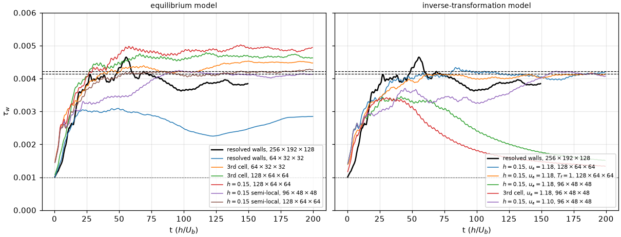
| Case | Cells | ||||
|---|---|---|---|---|---|
| resolved walls | 3.82e-3 | – | 211 ( | 1.16, 1.26 | |
| resolved walls | 2.35e-3 | 2.72e-3 | 166, 178 | 1.22, 1.26 | |
| equilibrium, 3rd cell | 4.37e-3 | 4.49e-3 | 226, 229 | 1.21, 1.29 | |
| equilibrium, 3rd cell | 4.36e-3 | 4.52e-3 | 226, 230 | 1.19, 1.30 | |
| equilibrium, 3rd cell | 4.69e-3 | 4.66e-3 | 234, 234 | 1.18, 1.31 | |
| equilibrium, 3rd cell, semi-local | 4.33e-3 | 4.33e-3 | 225, 225 | 1.18, 1.30 | |
| equilibrium, | 4.71e-3 | 4.77e-3 | 235, 236 | 1.19, 1.30 | |
| equilibrium, | 4.89e-3 | 4.90e-3 | 239, 239 | 1.19, 1.30 | |
| equilibrium, | 4.15e-3 | 4.09e-3 | 220, 219 | 1.18, 1.29 | |
| equilibrium, | 4.13e-3 | 4.21e-3 | 220, 222 | 1.17, 1.29 | |
| … and the filter | 4.15e-3 | 4.03e-3 | 220, 217 | 1.18, 1.29 | |
| … and the filter | 4.15e-3 | 4.16e-3 | 220, 221 | 1.19, 1.29 | |
| inverse, | 4.13e-3 | 4.08e-3 | 220, 218 | 1.16, 1.21 | |
| … and the filter | 4.04e-3 | 4.11e-3 | 217, 219 | 1.17, 1.21 | |
| inverse, | 2.03e-3 | 1.62e-3 | 154, 138: relaminarises | 1.51, 1.11 | |
| inverse, 3rd cell, | 1.61e-3 | 1.40e-3 | 137, 128: relaminarises | 1.44, 1.12 | |
| inverse, | 3.61e-3 | 4.15e-3 | 206, 220 | 1.18, 1.21 |
Every run conserves mass to
What it shows.
- Matching height 0.15 with semi-local damping puts the equilibrium model in the DNS band on both grids (219–222). Either change alone is worse: the 3rd-cell sample is 226–234 and rises with the grid,
with the classical damping 235–239, the semi-local damping at the 3rd cell 225. The fixed height removes the grid trend; the semi-local damping removes the excess. This is one Mach and Reynolds number, single runs, and the band sits within the of the wall density. - The input filter does not move the means (within 1.5 %); on the coarser grid it slows the transient.
- The inverse model is in the band on the finer grid with a cooler centreline (
1.21 against 1.29 for the equilibrium model, 1.26 for the resolved run): its heat flux differs. - On
the inverse model relaminarises with , at and at the 3rd cell, but not with . The model is sensitive to the given edge velocity, which the flow does not set (the paper takes the edge from the flow; a face kernel cannot). - The wall-resolved reference is 4–5 % short of the DNS (211). The modelled rows in the band agree with the DNS, not with it.
- The coarse grid with resolved walls falls 20 % short: without a model the grid cannot carry the wall layer.
Mach 3
Coleman, Kim & Moser's second case: bulk Mach 3, bulk Re 4880,
Result. With the wall model's eddy viscosity below wall_model_eddy_viscosity) and run to a thermal steady state at
Without a flux path below
| Setup | |
|---|---|
| run | channel_cases_t3_mach3.txt, to channel_cases_t3_mach3_drain.txt (the same runs, bitwise, a checkpoint every 500 steps) |
| the wall density changes with the run at this Mach number, so each row takes its own: | |
| the first cell (Favre, both walls) | |
wall heat flux over forcing work for channel_wall_cells.py budget; |
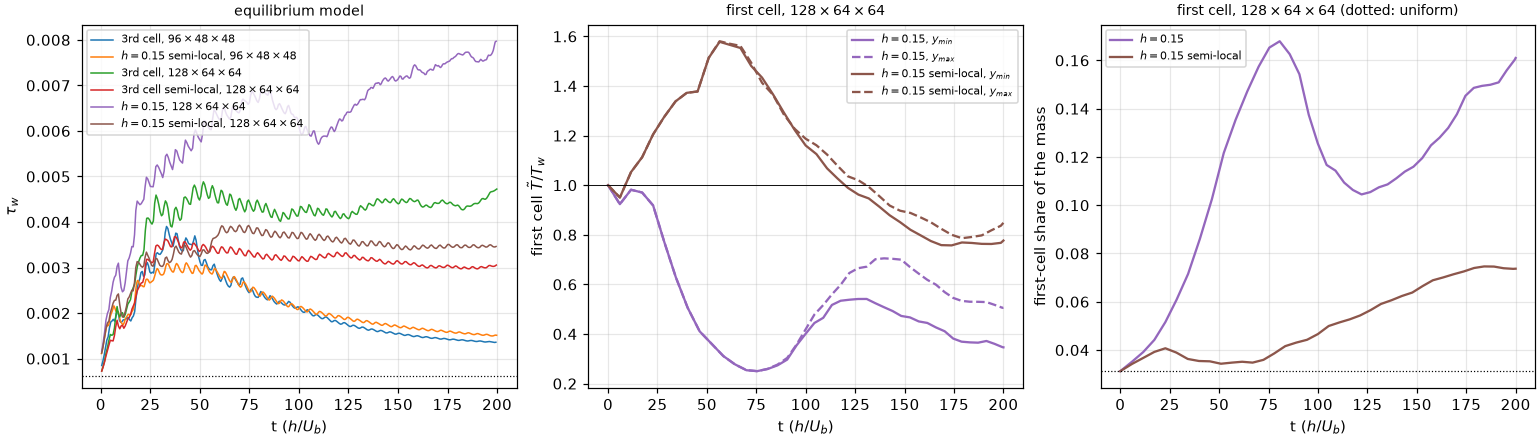
Left:
| Case | Cells | |||||||
|---|---|---|---|---|---|---|---|---|
| equilibrium, 3rd cell | 1.77e-3 | 1.43e-3 | 1.65 | 264, 238: relaminarises | 1.43, 1.63 | 0.86 | 0.71 | |
| equilibrium, | 1.89e-3 | 1.59e-3 | 1.54 | 263, 241: relaminarises | 1.50, 1.53 | 0.64 | 0.67 | |
| equilibrium, 3rd cell | 4.29e-3 | 4.44e-3 | 2.12 | 465, 473 | 1.25, 2.22 | 1.03 | 0.87 | |
| equilibrium, 3rd cell, semi-local | 3.20e-3 | 3.03e-3 | 2.02 | 392, 381 | 1.20, 2.04 | 1.28 | 0.85 | |
| equilibrium, | 3.58e-3 | 3.46e-3 | 1.91 | 404, 397 | 1.28, 2.01 | 0.81 | 0.83 | |
| equilibrium, | 6.46e-3 | 7.49e-3 | 2.12 | 571, 615: still rising | 1.48, 2.63 | 0.41 | 0.88 |
What it shows.
- No run is at a thermal steady state at
: the total energy still rises in every run ( 0.67–0.88), so these are values on the way, not means. - The Mach 1.5 setting does not carry over:
with semi-local damping is 12 % below the DNS; the 3rd-cell sample is 5 % above. The coarse grid relaminarises with either setting. - The first cell is drained. The wall face takes the modelled
and from the sample at ; the first cell's own state never enters, and nothing below carries those fluxes (no subgrid model): the molecular plus resolved stress at the face between cells 1 and 2 is 0.54 with semi-local damping and 0.21–0.39 with the classical one (after ). - With
and the classical damping the run does not settle. The first cell falls to , reverses its flow and holds 17 % of the mass at ; follows it, down ( 80–110) and up again. - With semi-local damping the drain is slower and
stays flat, but the first cell is still below from . A first cell colder than an isothermal wall that takes heat out of it is not a boundary layer: the treatment below fails, not the model's law.
With the eddy viscosity below
| Setup | |
|---|---|
| key | wall_model_eddy_viscosity = .true.: |
| runs | the three channel_cases_t3_mach3_ev.txt), continued from the restart to channel_cases_t3_mach3_ev800.txt) |
| measures |
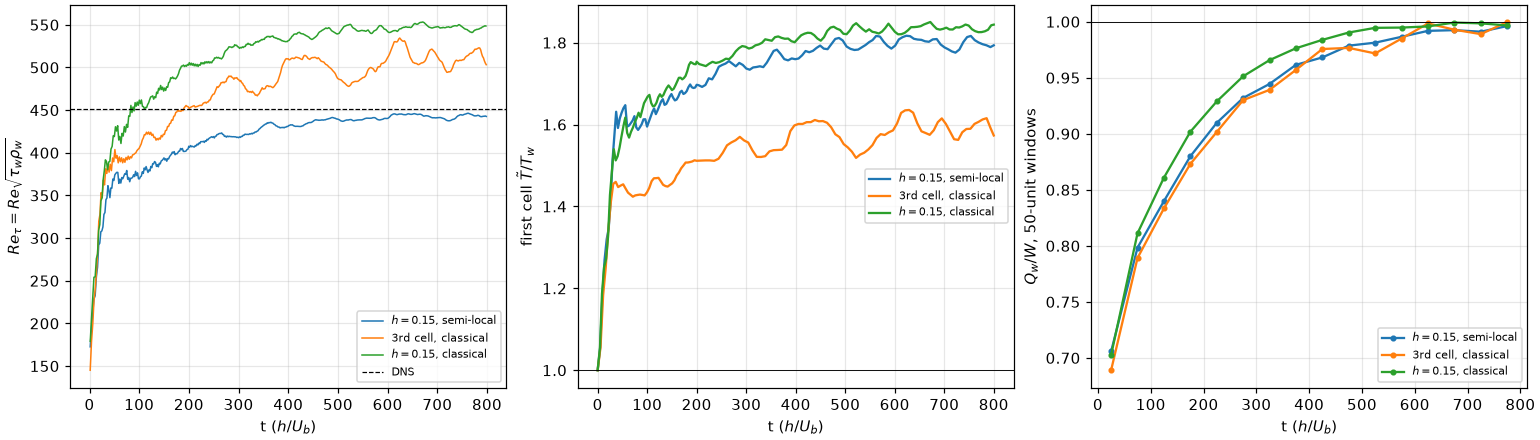
Left:
| Case | |||||||
|---|---|---|---|---|---|---|---|
| equilibrium, | 3.52e-3 | 3.48e-3 | 2.36 | 445, 443 | 1.17, 2.44 | 1.79 | 0.99 |
| equilibrium, 3rd cell | 4.51e-3 | 4.35e-3 | 2.51 | 519, 510 | 1.21, 2.65 | 1.57 | 0.99 |
| equilibrium, | 5.17e-3 | 5.15e-3 | 2.44 | 548, 547 | 1.21, 2.53 | 1.84 | 1.00 |
What it shows.
- The drain is gone. The first cell is
– at every time after the transient, the two walls agree within 2 %, and the two first-cell layers hold 4–5 % of the mass (3.1 % if uniform), against 16 % at without the key. - The runs are thermally steady at
: is 0.99–1.00 and about 60 times smaller than at . with semi-local damping matches the DNS within 2 %. With the classical damping is 13 % (3rd cell) and 21 % ( ) above. needs the thermal steady state at this Mach number. The bulk heats until , rises from about 2.1 to 2.4–2.5, and rises with it: at the 3rd-cell run gave 438, 448, which looked like a match. - Cost. From the same
state of the semi-local run to (4 A30), the key on takes 1.69 times the wall time of the key off: 1.28 times the steps (the eddy viscosity enters the viscous time-step limit) and 1.32 times the time per step.
The flow
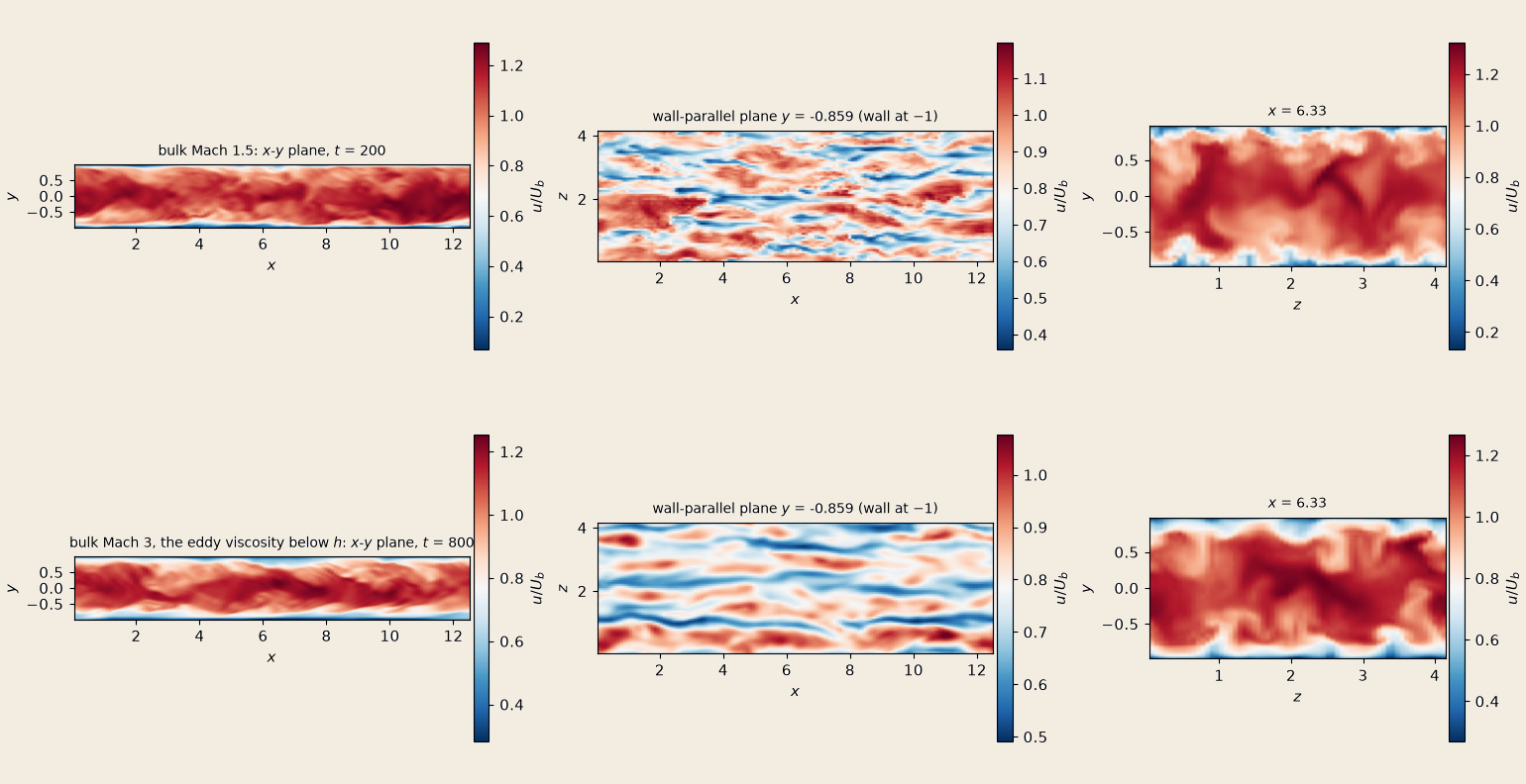
The streamwise velocity over the bulk velocity of the last checkpoint: the turbulence/field_slices.py; the figure is make_doc_figures.py --only channel-fields.
- At the matching height the flow is in streaks along
, but outer-scaled ones. At Mach 3 the first minimum of the spanwise correlation of in that plane puts them apart, about 470 wall units at , against the 100 of the near-wall cycle; at Mach 1.5 the correlation has no clear minimum within the span. The near-wall cycle lives below the matching height ( at Mach 1.5), in the wall model, and the grid ( , at Mach 1.5) does not form it above. - At Mach 3 the streaks look longer and more regular than at Mach 1.5. One snapshot each: a description, not a measurement.
Not done
- Averaged profiles against the DNS: only
and the centreline are compared, and the DNS profiles are not in this tree. - The cause of the wall-resolved reference's 4–5 % shortfall: its resolution or the hybrid scheme's dissipation.
- The relaminarisation of the inverse model on
with ; an edge state taken from the flow. - Why the classical damping overshoots at Mach 3; a cheaper flux path below
. - Runtime regridding along a modelled wall.