

15. Body-fitted grids
A body-fitted grid has its first grid line on the wall. FOSSIL does not generate such grids, but it supplies the geometry their generators and solvers need: points put on the body without crossing its edges, a 2-D hyperbolic O-grid marched out of a section, and a report of the wall spacing against a y₁⁺ target. The body of this chapter is the NACA0012 wing naca0012-ascii.stl (chord x ∈ [-0.25, 0.75], span z ∈ [0, 1], a blunt trailing edge 0.0025 thick). Its trailing edge is where an unconstrained projection goes wrong. The chapter takes four steps, one program each: the projection target, a block face projected onto the wing, an O-grid around its section, and the report on that O-grid.
The projection target
Every projection reads one structure, built once from the surface.
use fossil,     only : surface_stl_object, curve_object, projection_target_t, project_points, classify_points, &
                       slice_surface, PROJ_FREE, PROJ_PATCH, PROJ_CURVE, PROJ_CORNER
use fossil_fig, only : fig_open, fig_zoom, fig_surface, fig_segments, fig_points, fig_label, fig_close
use penf,       only : I4P, R8P
use vecfor,     only : vector_R8P

implicit none
integer(I4P), parameter   :: N = 6
type(surface_stl_object)  :: wing
type(projection_target_t) :: target
type(curve_object)        :: section
type(vector_R8P), allocatable :: a(:), b(:)
real(R8P)                 :: px(N), py(N), pz(N), ffx(N), ffy(N), ffz(N), fx(N), fy(N), fz(N)
integer(I4P)              :: kinds(N), ids(N), free(N), i, k, u
character(8)              :: num
character(16), parameter  :: NAME(0:3) = [character(16) :: 'PROJ_FREE', 'PROJ_PATCH', 'PROJ_CURVE', 'PROJ_CORNER']

call wing%load_from_file(file_name='naca0012-ascii.stl', guess_format=.true.) ! chord x in [-0.25, 0.75], span z in [0, 1]
call wing%projection_target(target)                                          ! built once: patches, curves, corners
print '(A,I0,A,I0,A,I0,A,I0,A,I0)', 'wing: ', wing%get_facets_number(), ' facets; target: patches ', target%np, &
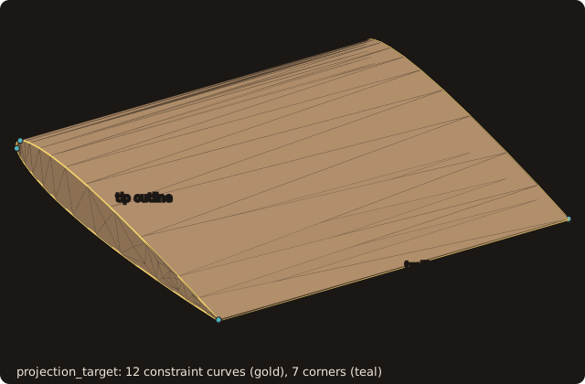
', constraint curves ', target%nc, ' (', size(target%seg, 2), ' segments), corners ', target%nkprojection_target(target)groups the triangles by named patch, with one tree per patch, and extracts the constraint curves and the corners. The curves are the feature edges of the surface (sharp, boundary, non-manifold;angle=sets the dihedral threshold, 30 degrees by default) plus the boundaries between patches, chained from corner to corner. A corner is a vertex where the constraint edges meet in a number other than two, or where a curve turns by more thancorner_angle(30 degrees).- The wing has one patch, 12 constraint curves made of 97 segments, and 7 corners (the run is in the next section). The curves are the root and tip outlines, the two trailing-edge lines and the edges of the blunt base. The corners are the four ends of the trailing-edge lines and three points of the root and tip outlines near the leading edge, where a polyline turns by more than 30 degrees.
Free and constrained projection
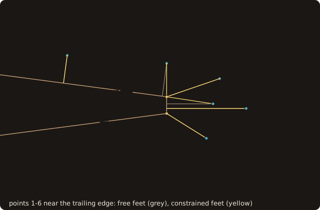
Six points around the trailing edge at mid-span are put on the wing in two ways.
px = [0.735_R8P, 0.75_R8P, 0.757_R8P, 0.758_R8P, 0.762_R8P, 0.756_R8P]                  ! around the trailing edge, mid-span
py = [0.0075_R8P, 0.0063_R8P, 0.0002_R8P, 0.0040_R8P, -0.0005_R8P, -0.005_R8P]
pz = 0.5_R8P
call classify_points(target, px, py, pz, tolerance=0.01_R8P, kinds=kinds, ids=ids)
free = PROJ_FREE
call project_points(target, px, py, pz, free, ids, ffx, ffy, ffz)   ! anywhere on the wing
call project_points(target, px, py, pz, kinds, ids, fx, fy, fz)     ! on the constraint found
do i = 1, N
   print '(A,I0,A,F6.3,A,F7.4,A,A12,I3,A,F7.4,A,F8.5,A,F7.4,A,F8.5,A)', 'point ', i, ' (', px(i), ',', py(i), '): ', &
         NAME(kinds(i)), ids(i), '  free (', ffx(i), ',', ffy(i), ')  constrained (', fx(i), ',', fy(i), ')'
enddo
classify_points(target, x, y, z, tolerance, kinds, ids)gives each point its constraint:PROJ_CORNERif a corner is within the tolerance, elsePROJ_CURVEif a constraint curve is, elsePROJ_PATCHwith the patch of the closest facet.idsis the corner, curve or patch.project_points(target, x, y, z, kinds, ids, fx, fy, fz, distances=, status=)moves each point to the closest point of its target: the whole surface (PROJ_FREE), one patch, one constraint curve (or any, id 0), one corner. Ties go to the lowest facet or segment index, so the result does not depend on the trees.
$ tut15_1_target
wing: 188 facets; target: patches 1, constraint curves 12 (97 segments), corners 7
point 1 ( 0.735, 0.0075): PROJ_PATCH    1  free ( 0.7344, 0.00331)  constrained ( 0.7344, 0.00331)
point 2 ( 0.750, 0.0063): PROJ_CURVE    6  free ( 0.7493, 0.00135)  constrained ( 0.7500, 0.00126)
point 3 ( 0.757, 0.0002): PROJ_CURVE    6  free ( 0.7500, 0.00020)  constrained ( 0.7500, 0.00126)
point 4 ( 0.758, 0.0040): PROJ_CURVE    6  free ( 0.7500, 0.00126)  constrained ( 0.7500, 0.00126)
point 5 ( 0.762,-0.0005): PROJ_PATCH    1  free ( 0.7500,-0.00050)  constrained ( 0.7500,-0.00050)
point 6 ( 0.756,-0.0050): PROJ_CURVE 3 free ( 0.7500,-0.00126) constrained ( 0.7500,-0.00126)- Points 1 and 5 are farther than 0.01 from every curve: they take the patch, and both projections agree. Point 5 lies behind the base and lands on it.
- Points 2, 3, 4 are within 0.01 of curve 6, the upper trailing-edge line, and point 6 of curve 3, the lower one. Free, point 2 lands on the upper surface at x = 0.7493, ahead of the edge, and point 3 on the base at y = 0.0002; constrained, both land on the edge itself, (0.75, 0.00126). A grid line meant to run along the edge would zig-zag across it with the free feet.
Projecting a block face
A block of chapter 13 whose face k = 1 lies over the upper side: 41 chordwise vertices, cosine-clustered towards the leading and trailing edges, by 21 spanwise. The face is projected twice, from two distances with two tolerances.
use fossil,     only : surface_stl_object, projection_target_t, curvilinear_block_t, project_block_face, &
                       PROJ_PATCH, PROJ_CURVE, PROJ_CORNER
use fossil_fig, only : fig_open, fig_zoom, fig_surface, fig_segments, fig_points, fig_label, fig_anim, fig_frame, fig_close
use penf,       only : I4P, R8P
use vecfor,     only : vector_R8P, ex_R8P

implicit none
real(R8P), parameter      :: PI = acos(-1._R8P)
real(R8P), parameter      :: OFFSET(2) = [0.005_R8P, 0.0005_R8P], TOLERANCE(2) = [0.01_R8P, 0.0014_R8P]
type(surface_stl_object)  :: wing
type(projection_target_t) :: target
type(curvilinear_block_t) :: block(2), block0(2)
real(R8P),    allocatable :: moved(:,:)
integer(I4P), allocatable :: kinds(:,:,:), k1(:,:)
integer(I4P)              :: t, i, status, u
character(8)              :: num

call wing%load_from_file(file_name='naca0012-ascii.stl', guess_format=.true.)
call wing%projection_target(target)
allocate(kinds(41, 21, 2))
block(1) = face_block(0._R8P)
print '(A,2F8.5)', 'last two chordwise steps at the trailing edge: ', block(1)%x(40, 1, 1) - block(1)%x(39, 1, 1), &
                                                                   block(1)%x(41, 1, 1) - block(1)%x(40, 1, 1)
do t = 1, 2
   block(t) = face_block(OFFSET(t))                ! layers k = 1, 2: face 5 is k = 1, the one near the wing
   block0(t) = block(t)
   call project_block_face(block(t), face=5_I4P, target=target, tolerance=TOLERANCE(t), moved=moved, &
                           kinds=k1, status=status)
   kinds(:, :, t) = k1
   print '(A,F7.4,A,F7.4,A,I0)', 'face ', OFFSET(t), ' off the wing, tolerance ', TOLERANCE(t), ': status ', status
   print '(A,I0,A,I0,A,I0,A,F7.4)', '  on corners ', count(kinds(:, :, t) == PROJ_CORNER), ', on curves ', &
         count(kinds(:, :, t) == PROJ_CURVE), ', on the patch ', count(kinds(:, :, t) == PROJ_PATCH), &
         ', largest move ', maxval(moved)
   print '(A,L1,A,L1,A,I0)', '  trailing-edge row on x = 0.75: ', all(block(t)%x(41, :, 1) == 0.75_R8P), &
         ', root and tip rows on z = 0, 1: ', all(block(t)%z(:, 1, 1) == 0._R8P) .and. all(block(t)%z(:, 21, 1) == 1._R8P), &
         ', face edges of zero length: ', zero_edges(block(t))
enddo
project_block_face(block, face, target, tolerance, moved=, kinds=, status=)classifies and projects every vertex of one face of acurvilinear_block_t, in place. The faces are numbered 1-6 = -i, +i, -j, +j, -k, +k: face 5 is k = 1.movedis the distance each vertex moved andkindsthe constraint it took. The other layers are not touched. In 2-D,project_block_side(block, side, target, tolerance, ...)does the same for one side of acurvilinear_block_2d_t, withclassify_points_2dandproject_points_2dbehind it.
$ tut15_2_face
last two chordwise steps at the trailing edge:  0.00461 0.00154
face  0.0050 off the wing, tolerance  0.0100: status 0
  on corners 7, on curves 132, on the patch 722, largest move  0.0085
  trailing-edge row on x = 0.75: T, root and tip rows on z = 0, 1: T, face edges of zero length: 42
face  0.0005 off the wing, tolerance  0.0014: status 0
  on corners 2, on curves 99, on the patch 760, largest move  0.0012
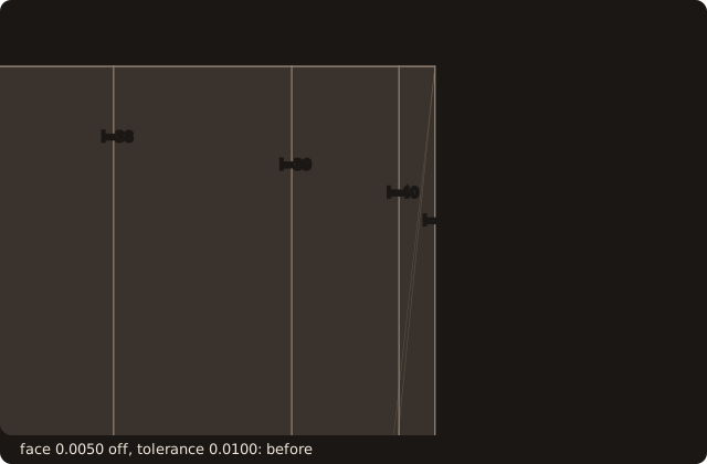
trailing-edge row on x = 0.75: T, root and tip rows on z = 0, 1: T, face edges of zero length: 0- The tolerance is a radius: every vertex within it of a curve goes onto the curve. With the face 0.005 off the wing it must exceed 0.005, or the trailing-edge row would take the patch and land beside the edge. But the last two chordwise steps are 0.00461 and 0.00154: with tolerance 0.01 the vertices i = 39 and 40 are within it of the trailing-edge line too, and all three go onto it. The trailing-edge row is on x = 0.75, as asked, and 42 face edges have zero length, two per spanwise station: degenerate cells.
- The tolerance has to exceed the distance from the face to the body and stay below the grid spacing next to the edges. With the face 0.0005 off the wing the largest move is 0.0012, below the tolerance 0.0014, which is below the last step 0.00154. The edge rows land on their curves (2 corners, 99 vertices on curves) and no edge collapses.
A hyperbolic O-grid
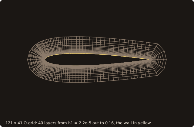
A 2-D grid around the mid-span section, with its first height set by a y₁⁺ target.
use fossil,     only : surface_stl_object, curve_object, curvilinear_block_2d_t, slice_surface, hyperbolic_grid_2d, &
                       geometric_spacing, utau_flat_plate
use fossil_fig, only : fig_open, fig_zoom, fig_segments, fig_quad, fig_anim, fig_frame, fig_close
use penf,       only : I4P, R8P
use vecfor,     only : vector_R8P

implicit none
type(surface_stl_object)     :: wing
type(curve_object)           :: section
type(curvilinear_block_2d_t) :: grid
real(R8P),        allocatable :: spacing(:), u(:), v(:)
type(vector_R8P), allocatable :: a(:), b(:)
real(R8P)                    :: nu, u_inf, u_tau, h1, p(2), q(2)
integer(I4P)                 :: i, j, k, m, first, last, invalid, status, un
character(96)                :: caption

call wing%load_from_file(file_name='naca0012-ascii.stl', guess_format=.true.)
call slice_surface(wing, normal_axis=3_I4P, level=0.5_R8P, curve=section)  ! the mid-span section, (u, v) = (x, y)
call section%get_loop_range(1_I4P, first, last)
allocate(u(2 * (last - first + 1)), v(2 * (last - first + 1)))
do i = first, last                                                     ! each segment split in 2: the same polygon
   p = section%get_vertex(i) ; q = section%get_vertex(merge(first, i + 1_I4P, i == last))
   do j = 0, 1
      u(2 * (i - first) + j + 1) = p(1) + (q(1) - p(1)) * j / 2._R8P
      v(2 * (i - first) + j + 1) = p(2) + (q(2) - p(2)) * j / 2._R8P
   enddo
enddo
print '(A,I0,A,I0,A)', 'section: ', last - first + 1, ' vertices, ', size(u), ' wall points'
nu = 1.e-6_R8P ; u_inf = 1._R8P                                        ! chord 1, Re = u_inf c / nu = 1e6
u_tau = utau_flat_plate(u_inf, nu, 0.5_R8P)                            ! flat-plate estimate at mid-chord
h1 = 1._R8P * nu / u_tau                                               ! y1+ = 1 by design: y1 = y1+ nu / u_tau
spacing = geometric_spacing(h1, 1.2_R8P, 40_I4P)                       ! 40 layers, ratio 1.2
print '(A,ES10.3,A,ES10.3,A,ES10.3,A,F7.4)', 'u_tau ', u_tau, ', h1 ', h1, ', last layer ', spacing(40), &
                                             ', outer height ', sum(spacing)
call hyperbolic_grid_2d(u, v, spacing, grid, invalid=invalid, status=status)
print '(A,I0,A,I0,A,I0,A,I0)', 'O-grid ', grid%ni, ' x ', grid%nj, ', status ', status, &
', cells not certified valid ', invalidslice_surface(chapter 7) gives the mid-span section, 60 vertices, counter-clockwise. Splitting each segment in two keeps the polygon and doubles the wall points to 120.- The first height comes from the y₁⁺ target: y₁ = y₁⁺ ν / u_τ.
utau_flat_plate(u_inf, nu, x)estimates u_τ for a turbulent flat plate, C_f = 0.0576 Re_x^(−1/5), u_τ = U sqrt(C_f / 2). At Re = 10⁶ and mid-chord it gives u_τ = 4.569e-2, so h₁ = 2.189e-5 for y₁⁺ = 1. geometric_spacing(h1, ratio, layers)returns the layer heights h₁ qᵏ⁻¹: 40 layers with ratio 1.2 reach 0.1607 from the wall, the last one 2.681e-2 high.hyperbolic_grid_2d(u, v, spacing, block, closed=, epsilon=, invalid=, status=)marches the layers outward from a closed curve (counter-clockwise;closed=.false.for an open one). Each step is normal to the current layer, with the mitre length h / cos(β/2) at a point where the layer turns by β, so a layer stays at height h from both sides of a corner. The step directions are smoothed implicitly, more in the outer layers (epsilon, 0.5 at most by default). The result is acurvilinear_block_2d_tof 121 × 41 vertices (the first point repeated at i = 121). Every cell is checked by the certified Jacobian of the curvilinear blocks:status = 2withinvalid > 0reports a fold.
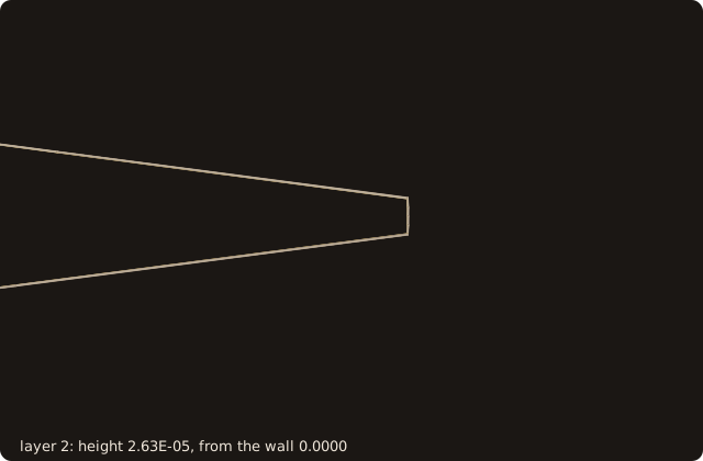
do k = 10, 40, 10                                                      ! layer k: its height, the distance marched
   print '(A,I2,A,ES10.3,A,ES10.3)', 'layer ', k, ': height ', spacing(k), ', from the wall ', sum(spacing(1:k))
enddo
$ tut15_3_ogrid
section: 60 vertices, 120 wall points
u_tau 4.569E-02, h1 2.189E-05, last layer 2.681E-02, outer height 0.1607
O-grid 121 x 41, status 0, cells not certified valid 0
layer 10: height 1.129E-04, from the wall 5.682E-04
layer 20: height 6.993E-04, from the wall 4.086E-03
layer 30: height 4.330E-03, from the wall 2.587E-02
layer 40: height 2.681E-02, from the wall 1.607E-01- No cell fails the certified validity. The heights grow by 1.2 per layer: 1.129e-4 at layer 10, 4.330e-3 at layer 30. The first 20 layers fill only 4.086e-3, the last 10 more than 0.13.
The wall-spacing report
The last program rebuilds the O-grid of step 3 and checks what it delivers.
rec%kind = TOPO_BOUNDARY ; rec%face = 3 ; rec%lo = [1, 1, 1] ; rec%hi = [grid(1)%ni, 1, 1] ; rec%name = 'wall'
call grid(1)%add_record(rec)                                            ! side j = 1 is the wall
call wall_cutter_2d(grid, wall)                                         ! the wall as a curve
call block_report_2d(grid(1), wall, nu, report, u_tau=u_tau, target_y1p=1._R8P)
print '(A,I0,A,3F8.4,A,F6.3)', 'u_tau given, ', report%nw, ' wall points: y1+ min mean max', report%y1p_min, &
                               report%y1p_mean, report%y1p_max, ', above target ', report%above
m = maxloc(report%y1p, dim=1)
print '(A,F7.4,A,I0,A,2F9.5,A)', '  max ', report%y1p(m), ' at wall point ', report%point(1, m), ', (x, y) = (', &
                                 grid(1)%u(report%point(1, m), 1), grid(1)%v(report%point(1, m), 1), ')'
print '(A,ES10.3,A,ES10.3)', '  y1_line there ', report%y1_line(m), ', y1_wall ', report%y1_wall(m)
print '(A,F7.4,A,F7.4,A,F7.4,A,I0)', '  growth max ', report%growth_max, ', skewness max ', report%skew_max, &
                                     ', orthogonality min ', report%orth_min, ', not valid ', report%not_valid
call grid(1)%quality(orthogonality=orth)                                ! the cells behind the minimum (chapter 13)
print '(A,I0,A,I0,A,2I3)', '  cells with orthogonality < 0.5: ', count(orth < 0.5_R8P), ' of ', size(orth), &
', the worst (i, j) =', minloc(orth)- The report reads the wall from the block's topology records (chapter 13): every
TOPO_BOUNDARYrecord namedwall, here the side j = 1.wall_cutter_2d(blocks, curve)turns those sides into a curve, the true wall. block_report_2d(block, cutter, nu, report, ...)(block_reportfor a 3-D block and a surface cutter) measures per wall pointy1_line, the first step along the wall-normal grid line, andy1_wall, the distance of the first off-wall point to the cutter: the true height, smaller when the grid line leaves the wall at an angle. Theny1p= y1_wall u_τ / ν,growth, the largest ratio of consecutive steps along the grid line, and over the block the cell quality of chapter 13: skewness, orthogonality, aspect, certified validity.- u_τ is given here,
u_tau=for all points (u_tau_wall=per point), the value the first height was designed with.
call block_report_2d(grid(1), wall, nu, estimate, u_inf=u_inf, x_le=-0.25_R8P, target_y1p=1._R8P)
print '(A,L1,A,3F8.4,A,F6.3)', 'flat-plate u_tau (estimated ', estimate%utau_estimated, '): y1+ min mean max', &
                               estimate%y1p_min, estimate%y1p_mean, estimate%y1p_max, ', above target ', estimate%above
m = maxloc(estimate%y1p, dim=1)
print '(A,F7.4,A,2F9.5,A)', '  max ', estimate%y1p(m), ' at (x, y) = (', grid(1)%u(estimate%point(1, m), 1), &
grid(1)%v(estimate%point(1, m), 1), ')'- Without a solver's u_τ,
u_inf=and the leading edgex_le=make the report estimate it at each wall point by the flat-plate correlation, with x − x_le as the distance (utau_estimatedis then true).
call save_block_report(report, 'tut15-report.txt')
open(newunit=unit, file='tut15-report.txt', action='read')
do i = 1, 7
   read(unit, '(A)') line
   if (i /= 5) print '(A)', trim(line)                                  ! line 5, the cell quality, is long
enddo
close(unit)
save_block_report(report, file_name)writes the totals (#lines) and one line per wall point: indices, face, y1_line, y1_wall, y1+, growth.
$ tut15_4_report
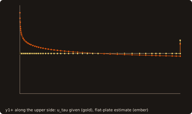
u_tau given, 121 wall points: y1+ min mean max  0.9999  1.0065  1.3303, above target  0.752
  max  1.3303 at wall point 57, (x, y) = (  0.75000 -0.00126)
  y1_line there  2.912E-05, y1_wall  2.912E-05
  growth max  1.2031, skewness max  0.9029, orthogonality min  0.0193, not valid 0
  cells with orthogonality < 0.5: 4 of 4800, the worst (i, j) = 56  1
flat-plate u_tau (estimated T): y1+ min mean max  0.0000  1.1961  2.0163, above target  0.744
  max  2.0163 at (x, y) = ( -0.24955  0.00174)
# FOSSIL block report (issue #74)
# wall points 121, cell centred F, u_tau given T, u_tau estimated (flat plate) F
# y1+ min max mean p95   9.998535E-01  1.330332E+00  1.006542E+00  1.006843E+00  target   1.0000E+00  fraction above   0.7521
# growth ratio max   1.203074E+00
# i j k face y1_line y1_wall y1+ growth
1 1 1 3 2.26018677E-05 2.26018677E-05 1.03262723E+00 1.20069196E+00- With the u_τ it was designed for, y₁⁺ has minimum 0.9999 and mean 1.0065: the O-grid delivers its target. The maximum, 1.3303, is at a corner of the blunt trailing edge, (0.75, -0.00126), where the first step is 2.912e-5 instead of 2.189e-5: the mitre step keeps the first point h₁ from both sides of the corner, so h₁ / cos(β/2) from the corner vertex itself.
abovecounts every point with y₁⁺ > 1, round-off excess included: 0.752. - The growth ratio stays at 1.2 (1.2031 at most), and no cell fails the certified validity. Skewness reaches 0.9029 and orthogonality falls to 0.0193 at the wall cells beside the trailing-edge corners, where the fan turns cells 2e-5 high: 4 of the 4800 cells are below 0.5.
- With the flat-plate estimate y₁⁺ is 0 at the leading edge, where x − x_le = 0 and the estimate gives u_τ = 0, and 2.0163 just behind it, at x = -0.24955, where Re_x is small and the estimate large. It crosses the designed value at x = 0.25, where x − x_le = 0.5 is the distance the design u_τ was taken at, and falls below it behind. Such estimates can be about 300 % off near a leading edge: use them to size a grid before a run, then pass the solver's own u_τ (
u_tau_wall=) to check it after.
What you learned
projection_target once, then classify_points / project_points or project_block_face to put grid points on a body without crossing its edges, with a tolerance above the distance to the body and below the spacing at the edges; geometric_spacing from a y₁⁺ target and hyperbolic_grid_2d for an O-grid; block_report_2d / block_report and save_block_report to check the wall spacing and the cells. Reference: Body-fitted grid support, Curvilinear blocks.
Next: 16. On the GPU.