

Body-fitted grid support
Body-fitted grids are generated by other tools. Those tools, and the solvers that run on their grids, need three things that are geometry:
- putting grid points on the body without crossing its features;
- measuring a grid's fitness for a wall-bounded solver;
- in 2-D, the simplest generator that needs only a boundary.
Issue #74 (roadmap #68, WP5) adds them in the module fossil_projection and as routines on the curvilinear blocks.
Design and reference (issue #74)
Sources are the llm-wiki bundles overset-grid-methods and turbulence-modelling, with pages cited by path. Statements from general knowledge are marked (gk). CPU only: these are set-up computations.
At a glance
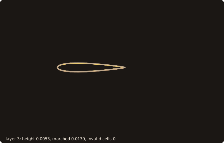
hyperbolic_grid_2d marches 24 layers out of a NACA 0012 section, first height 4e-3 chord, growth 1.15; each frame shows three more layers of the block, up to 0.7367 chord from the wall, with 0 cells not certified valid (anim_hyperbolic.f90).
Why projection needs constraints
NASA's overset tool chain marches surface grids and projects them back on the body at each step. It calls surface grid generation "the most difficult grid generation step" (overset-grid-methods/wiki/sources/chan-2009.md).
The closest point on a surface is the wrong target for a grid point near a sharp edge: the point lands on whichever face is nearer, and a grid line that should run along the edge zig-zags across it. A projection therefore takes a constraint per point:
| Kind | Target | Use |
|---|---|---|
PROJ_FREE | the whole surface | interior points far from features |
PROJ_PATCH | one named patch (#66) | points of a face grid on one patch |
PROJ_CURVE | one constraint curve, or any | grid lines along an edge or a patch boundary |
PROJ_CORNER | one corner, fixed | grid corners on body corners |
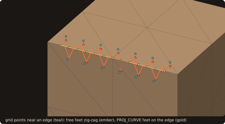
On cube-01.stl (12 constraint curves, 8 corners), 7 of the 13 free feet land on the top face and 6 on the front face, each 0.08 off the edge; with PROJ_CURVE and id 0 (any curve) all 13 lie on the edge (fig_ref_body_fitted_zigzag.f90).
The projection target
A projection_target_t is built once from a surface (2-D: a curve) and every query reads it. It holds:
- the triangles with their patch, and one bounding-volume tree per patch;
- the constraint curves: the feature edges of #61 (sharp, boundary, non-manifold) and the patch boundaries (edges between facets of different patches, always included), chained into polylines between corners, with one segment tree over them;
- the corners: the vertices where the constraint edges meet in a number other than two, or turn by more than
corner_angle(default 30 degrees).
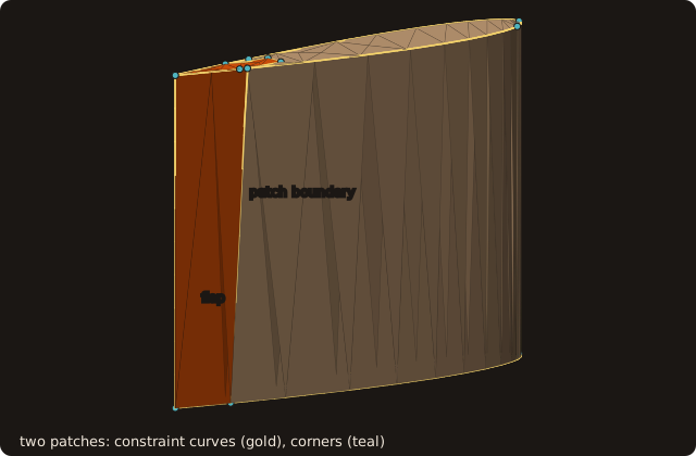
The wing of the test bodies (188 facets) with its rear facets moved to a patch flap has 27 constraint curves and 18 corners (fig_ref_body_fitted_target.f90). The patch boundaries are constraint curves although the surface is smooth across them, so a grid line can be held on the edge of the flap.
In 2-D, a curve's constraint points are its corners (feature_corners) and the points where two patches meet. A PROJ_CURVE constraint has no 2-D meaning.
Projection and classification
project_points(target, x, y, z, kinds, ids, fx, fy, fz, distances) gives each point its foot on its target:
- the closest point on a triangle (
closest_on_triangle, accurate to ~eps L on needles, #69); - or on a segment (clamped projection);
- or the corner itself.
Ties go to the lowest triangle or segment index, so the result is deterministic. Projecting a foot again moves it by round-off only.
classify_points(target, x, y, z, tolerance, kinds, ids) tags points automatically:
- within
toleranceof a corner:PROJ_CORNER; - else within it of a constraint curve:
PROJ_CURVE; - else
PROJ_PATCHwith the patch of the nearest facet.
project_block_face(block, face, target) classifies and projects the vertices of one face of a block in place (2-D: project_block_side). Its corners go to corners, edge vertices to curves, and interior vertices stay on their patch.
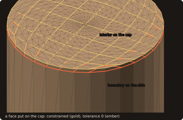
With tolerance 0.07 the 32 boundary vertices of the squircle face are classified PROJ_CURVE and land on the rim, the 49 interior ones PROJ_PATCH on the cap. With tolerance 0 all 81 are PROJ_PATCH, and the boundary row, nearer the side than the cap, stays on the side at z = 1.95 (fig_ref_body_fitted_face.f90).
The wall-spacing report
Wall-resolved RANS asks for a first-cell height y₁⁺ ~ 1 with finite volumes and ~ 10 with DG. Wall functions sit at y⁺ ≈ 30-100 (turbulence-modelling/wiki/methods/rans-wall-function.md), and LES ranges are in results/les-grid-point-requirements.md. block_report measures a block against such a target, per wall vertex (the faces covered by TOPO_BOUNDARY records named wall):
- y₁ along the grid line: |x₂ − x₁|, the first off-wall vertex along the wall-normal index. With
cell_centred=.true.the report is per wall cell instead: the distance from the centre of the cell's wall face (mean of its 4 vertices, 2-D 2) to the centre of the first cell (mean of its 8 vertices, 2-D 4). - y₁ to the wall: the distance of the off-wall point (vertex or cell centre) to the wall cutter (
wall_cutter, WP3): the true height, which differs from the grid-line one when the grid line leaves the wall at an angle. - y₁⁺ = y₁ u_τ / ν, with u_τ given by the caller (a scalar, or one value per wall vertex). Otherwise it is estimated from a flat-plate correlation (
utau_flat_plate: C_f = 0.0576 Re_x^(−1/5), u_τ = U sqrt(C_f/2) (gk: Schlichting)) and flagged as an estimate. Such estimates can be about 300 % off at a leading edge (turbulence-modelling/wiki/methods/immersed-boundary-method.md). - The wall-normal growth ratio h_{k+1}/h_k along the grid line.
The report also summarises WP2's metrics over the whole block:
- min, max, mean and the 95th percentile of skewness, orthogonality, aspect and warp;
- the number of cells certified invalid or undetermined.
It gives the fraction of wall vertices above target_y1p. save_block_report writes the totals and one line per wall vertex as plain text.
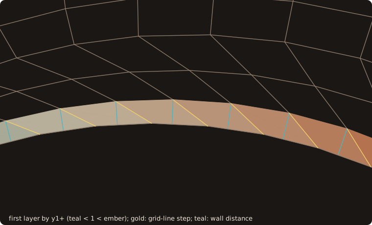
An O-grid of 64 × 12 cells around the unit circle, first height 0.04 (1 + 0.5 cos θ), its first layers sheared on the upper half; block_report_2d with u_τ = 1 and ν = 0.04. y₁⁺ runs from 0.5 to 1.5 (mean 1.017), and 52.3 % of the wall vertices are above the target 1. At wall vertex 17, the top, the step along the sheared grid line is 0.07309 and the height to the wall 0.04114, which gives y₁⁺ = 1.0286 (fig_ref_body_fitted_report.f90).
Hyperbolic extrusion (2-D)
Hyperbolic grids are "one to two orders of magnitude faster" to generate than elliptic ones. They march from one boundary and cannot place the outer one, which suits overset grids (Chan 2009). Overture re-marches its body-fitted grids this way for moving bodies (overset-grid-methods/wiki/software/overture.md).
hyperbolic_grid_2d(u, v, spacing, block) marches layers outward from a closed curve (an O-grid) or an open one, to the right of the curve's direction (outward for a counter-clockwise closed curve) (gk: Steger & Chaussee 1980).
- The step. The two conditions of the hyperbolic system are orthogonality, r_ξ · r_η = 0, and the cell size, |r_ξ × r_η| = ΔA. They give at each point a step normal to the current layer (central differences).
- The mitre length. Its length is h / cos(β/2), with h the layer's height and β the layer's turning angle at the point (capped at 4h). This is the exact offset of a polygon: a layer stays at height h from both sides of a corner. A plain h along the bisector makes concave corners lag and their cells fold. From a regular polygon the layers are its exact offsets.
- Smoothing. The step directions are smoothed by an implicit dissipation, (I − ε_k δ_ξξ) D = n: a periodic or plain tridiagonal solve per layer, with ε_k growing linearly to
epsilon(default 0.5) at the last layer. - Validity. Every generated cell is checked by WP2's quality (scaled certified min J).
invalidcounts the cells not certified valid, and status 2 reports them. - Measured limit. The smoothing cures a V-shaped concave corner (a notch 0.15 deep in a unit square folds without it, not with it). It does not cure a right-angled concave notch once the marched height passes the point spacing at its corners: a structured layer cannot drop the points that the offset of a concave corner swallows. The status reports the folds, and the caller limits the height or refines the boundary there.
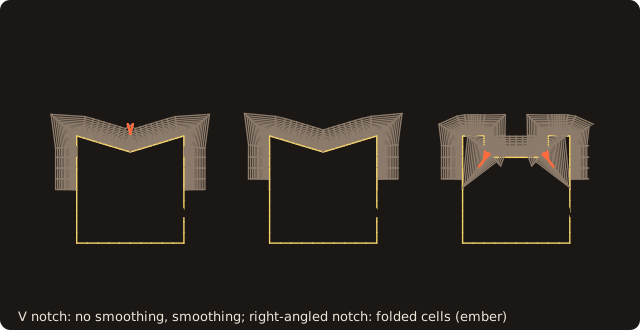
The V notch folds 4 cells with epsilon=0 and none with the default 0.5; the right-angled notch folds 26 cells even with it, and status is 2 (fig_ref_body_fitted_notch.f90).
- Spacing.
geometric_spacing(h1, ratio, layers)gives the layer heights. The first height can be set from a y₁⁺ target with the report's definitions (y₁ = y₁⁺ ν / u_τ).
Example
The wing of the figure above, with its flap, then an O-grid around a NACA 0012 section and its report. Cookbook recipes cover the plain cases: a block face on a cube and an O-grid with a given u_τ.
program ref_body_fitted
use fossil,              only : surface_stl_object, projection_target_t, classify_points, project_points, &
                                PROJ_FREE, PROJ_PATCH, PROJ_CURVE, PROJ_CORNER, curve_object, curvilinear_block_2d_t, &
                                topo_record_t, TOPO_BOUNDARY, hyperbolic_grid_2d, geometric_spacing, wall_cutter_2d, &
                                block_report_t, block_report_2d, save_block_report, utau_flat_plate
use fossil_facet_object, only : facet_object
use penf,                only : I4P, R8P
implicit none
character(6), parameter      :: KIND_NAME(4) = ['free  ', 'patch ', 'curve ', 'corner']
real(R8P), parameter         :: PI = acos(-1._R8P), NU = 1.5e-5_R8P, U_INF = 10._R8P
type(surface_stl_object)     :: wing
type(facet_object), pointer  :: f
type(projection_target_t)    :: target
type(curvilinear_block_2d_t) :: grid(1)
type(curve_object)           :: wall
type(topo_record_t)          :: rec
type(block_report_t)         :: report
integer(I4P), allocatable    :: flap(:)
real(R8P)                    :: px(4), py(4), pz(4), fx(4), fy(4), fz(4), d(4), gx(4), gy(4), gz(4), e(4)
real(R8P)                    :: u(129), v(129), xc, yt
integer(I4P)                 :: kinds(4), ids(4), i, invalid, status
character(160)               :: line

call wing%load_from_file(file_name='naca0012-ascii.stl', guess_format=.true.) ! chord x in [-0.25, 0.75], span z in [0, 1]
allocate(flap(0))
do i = 1, wing%get_facets_number() ! the rear facets become the patch 'flap'
   f => wing%facet_at(i)
   if (min(f%vertex(1)%x, f%vertex(2)%x, f%vertex(3)%x) >= 0.45_R8P) flap = [flap, i]
enddo
call wing%set_patch(flap, 'flap')
call wing%projection_target(target) ! sharp edges above 30 degrees, patch boundaries, corners
print '(A,I0,A,I0,A,I0)', 'target: patches ', target%np, ', constraint curves ', target%nc, ', corners ', target%nk

px = [0.745_R8P, 0.74_R8P, 0.57_R8P, 0.2_R8P]  ! near the trailing-edge corner at the root, near the trailing edge,
py = [0.004_R8P, 0.004_R8P, 0.03_R8P, 0.07_R8P] ! near the upper patch boundary, above the upper surface
pz = [0.01_R8P, 0.5_R8P, 0.4_R8P, 0.5_R8P]
call classify_points(target, px, py, pz, tolerance=0.02_R8P, kinds=kinds, ids=ids)
call project_points(target, px, py, pz, kinds, ids, fx, fy, fz, distances=d)
call project_points(target, px, py, pz, [(PROJ_FREE, i = 1, 4)], [(0_I4P, i = 1, 4)], gx, gy, gz, distances=e)
do i = 1, 4
   print '(A,I0,3A,I0,A,3F9.5,A,F8.5)', 'point ', i, ': ', trim(KIND_NAME(kinds(i) + 1)), ' ', ids(i), ', foot', fx(i), fy(i), &
                                       fz(i), ', moved ', d(i)
   print '(A,3F9.5,A,F8.5)', '         free foot          ', gx(i), gy(i), gz(i), ', moved ', e(i)
enddo
! a point above the main patch, constrained to the flap
call project_points(target, [0.45_R8P], [0.05_R8P], [0.5_R8P], [PROJ_PATCH], [2_I4P], fx(1:1), fy(1:1), fz(1:1), &
                    distances=d(1:1))
print '(A,3F9.5,A,F8.5)', '(0.45, 0.05, 0.5) on the flap ', fx(1), fy(1), fz(1), ', moved ', d(1)

do i = 1, 129 ! a NACA 0012 section, chord 1, counter-clockwise from the trailing edge
   xc = 0.5_R8P * (1._R8P + cos(2 * PI * (i - 1) / 129._R8P))
   yt = 0.6_R8P * (0.2969_R8P * sqrt(xc) - 0.126_R8P * xc - 0.3516_R8P * xc**2 + 0.2843_R8P * xc**3 - 0.1015_R8P * xc**4)
   u(i) = xc ; v(i) = merge(yt, -yt, i <= 65)
enddo
call hyperbolic_grid_2d(u, v, geometric_spacing(2.e-5_R8P, 1.15_R8P, 50_I4P), grid(1), invalid=invalid, status=status)
print '(A,I0,A,I0,A,I0,A,I0)', 'O-grid ', grid(1)%ni, ' x ', grid(1)%nj, ', status ', status, ', not valid ', invalid
rec%kind = TOPO_BOUNDARY ; rec%face = 3 ; rec%lo = [1, 1, 1] ; rec%hi = [grid(1)%ni, 1, 1] ; rec%name = 'wall'
call grid(1)%add_record(rec)
call wall_cutter_2d(grid, wall)
print '(A,F8.5)', 'flat-plate u_tau at mid-chord ', utau_flat_plate(U_INF, NU, 0.5_R8P)
call block_report_2d(grid(1), wall, NU, report, u_inf=U_INF, x_le=0._R8P, target_y1p=1._R8P, cell_centred=.true.)
print '(A,I0,A,L1,A,L1)', 'wall cells ', report%nw, ', cell centred ', report%cell_centred, ', u_tau estimated ', &
                          report%utau_estimated
print '(A,3F8.4,A,F6.3)', 'y1+ min mean max ', report%y1p_min, report%y1p_mean, report%y1p_max, &
                          ', fraction above 1 ', report%above
i = maxloc(abs(report%y1_line - report%y1_wall), 1)
print '(A,ES10.3,A,ES10.3,A,I0)', 'y1 along the line ', report%y1_line(i), ', to the wall ', report%y1_wall(i), &
                                  ' at wall cell ', i
print '(A,F7.4,A,F7.4,A,I0)', 'growth max ', report%growth_max, ', skewness max ', report%skew_max, &
                              ', cells not valid ', report%not_valid
call save_block_report(report, 'naca_report.txt')
open(newunit=i, file='naca_report.txt', action='read')
read(i, '(A)') line ; print '(A)', trim(line)
read(i, '(A)') line ; print '(A)', trim(line)
read(i, '(A)') line ; print '(A)', trim(line)
close(i)
endprogram ref_body_fitted
$ ref_body_fitted
target: patches 2, constraint curves 27, corners 18
point 1: corner 4, foot 0.75000 0.00126 0.00000, moved 0.01151
free foot 0.74474 0.00194 0.01000, moved 0.00208
point 2: curve 9, foot 0.75000 0.00126 0.50000, moved 0.01037
free foot 0.73982 0.00261 0.50000, moved 0.00141
point 3: curve 12, foot 0.57833 0.02299 0.40043, moved 0.01090
free foot 0.56935 0.02395 0.40000, moved 0.00609
point 4: patch 1, foot 0.19928 0.05549 0.50001, moved 0.01453
free foot 0.19928 0.05549 0.50001, moved 0.01453
(0.45, 0.05, 0.5) on the flap 0.57342 0.02355 0.50589, moved 0.12636
O-grid 130 x 51, status 0, not valid 0
flat-plate u_tau at mid-chord 0.47578
wall cells 129, cell centred T, u_tau estimated T
y1+ min mean max 0.1784 0.3443 0.7145, fraction above 1 0.000
y1 along the line 9.480E-06, to the wall 6.026E-06 at wall cell 1
growth max 1.1520, skewness max 0.9113, cells not valid 0
# FOSSIL block report (issue #74)
# wall points 129, cell centred T, u_tau given F, u_tau estimated (flat plate) T
# y1+ min max mean p95 1.783578E-01 7.145332E-01 3.442948E-01 4.982101E-01 target 1.0000E+00 fraction above 0.0000- The target.
projection_targetbuilds the per-patch trees, the 27 constraint curves and the 18 corners once. - Classification.
classify_pointswith tolerance 0.02 tags the four pointsPROJ_CORNER(corner 4, the trailing-edge corner at the root),PROJ_CURVE(curve 9, the upper trailing-edge line; curve 12, the upper patch boundary) andPROJ_PATCH(patch 1). - Constrained against free feet. The first three feet sit on the corner, the line and the patch boundary; the free feet of the same points land on the faces next to them, nearer (0.00208 against 0.01151 for the first point) but off the feature. The fourth point is far from every feature, and both feet agree.
- One patch.
PROJ_PATCHwith id 2 keeps (0.45, 0.05, 0.5) on the flap: its foot is the flap's nearest point, 0.12636 away, at the patch boundary. - Extrusion.
hyperbolic_grid_2dmarches 50 layers from 2e-5 chord with growth 1.15: 130 × 51 vertices (the closed curve repeats its first point), every cell certified valid. - The report. Without
u_tau,u_infandx_leselect the flat-plate estimate (u_τ = 0.47578 at mid-chord for U = 10, ν = 1.5e-5), and the report says so. Withcell_centred=.true.there is one line per wall cell, 129. The two heights differ most at wall cell 1, the trailing edge, where the grid line leaves the wall at an angle: 9.480e-6 along the line, 6.026e-6 to the wall.save_block_reportwrites the totals as#lines, then one line per wall cell.
API
| Routine | Arguments |
|---|---|
surface%projection_target(target, angle, corner_angle) / curve%projection_target(target, corner_angle) | build |
project_points(target, x, y, z, kinds, ids, fx, fy, fz, distances) / project_points_2d | constrained feet |
classify_points(target, x, y, z, tolerance, kinds, ids) / classify_points_2d | automatic constraints |
project_block_face(block, face, target, tolerance, moved, kinds, status) / project_block_side | a block face onto the body, in place |
block_report(block, cutter, nu, report, u_tau, u_tau_wall, u_inf, x_le, target_y1p, cell_centred, wall_name, status) / block_report_2d | wall spacing and quality (fossil_block_report) |
save_block_report(report, file_name), utau_flat_plate(u_inf, nu, x) | the text file, the flat-plate estimate |
hyperbolic_grid_2d(u, v, spacing, block, closed, epsilon, invalid, status), geometric_spacing(h1, ratio, layers) | 2-D extrusion (fossil_hyperbolic) |
Proved and measured
- Exact by construction: corners are returned bit for bit; feet on a given constraint are its closest points (ties by index); the classification is deterministic.
- Measured (
fossil_test_projection*,fossil_test_block_report,fossil_test_hyperbolic_2d,fossil_val_body_fitted):
| Case | Result |
|---|---|
| a point near a cube edge | free projection lands on the wrong face; PROJ_PATCH and PROJ_CURVE do not |
| projection idempotence | 3.4 ulps on a sphere; 3.5e-13 on the NACA0012 wing (feet on edges of long spanwise triangles) |
| a cylinder rim | feet equal the closest chord point, bit for bit |
| a squircle face under a cylinder cap | boundary on the rim, interior on the cap; unconstrained, the boundary falls on the side |
| NACA0012 wing, a 41 × 21 grid | trailing-edge row on its line, root and tip rows on z = 0 and 1, corners on corners |
| geometric O-grids (2-D, 3-D) | y₁ = h₁ along the line and to the wall to 2e-16, growth ratio q to 1e-12 |
| NACA0012 O-grid, y₁⁺ = 1 by design | every cell valid; y₁⁺ 1.000-1.009 away from the trailing edge, 1.48 at its corner |
| extrusion from a regular 64-gon | its exact offsets, to 7e-16 |
| a V notch 0.15 deep / a right-angled notch | folds without smoothing, none with it / folds reported (26 cells) |
| the bunny (69 451 facets) | target built in 0.06 s; a 101 × 101 grid projected in 0.73 s |
Left out
- Surface grid generation (marching on surfaces, collar grids at junctions): the projection is the kernel such a generator needs.
- Elliptic smoothing; 3-D hyperbolic extrusion, which needs a structured surface grid first.
- Unstructured and prismatic layer meshing; device kernels.